
Communication apparatus, storage medium, camera and processing method

a technology of communication apparatus and storage medium, applied in closed-circuit television systems, two-way working systems, television systems, etc., can solve problems such as the symbol of the camera not matching the state of the actual video camera

Inactive Publication Date: 2007-05-22
CANON KK
View PDF6 Cites 361 Cited by
  • Summary
  • Abstract
  • Description
  • Claims
  • Application Information

AI Technical Summary

Benefits of technology

[0008]An object of the present invention is to provide a communication apparatus, a storage medium, a camera and a processing method whi

Problems solved by technology

In this case, as long as the terminal which utilizes that map does not obtain a state update of the video camera concerned, a problem exists in that the state of the camera symbol does not correspond to the state of the actual video camera.

Method used


Image

  • Communication apparatus, storage medium, camera and processing method
  • Communication apparatus, storage medium, camera and processing method
  • Communication apparatus, storage medium, camera and processing method

Examples


first embodiment

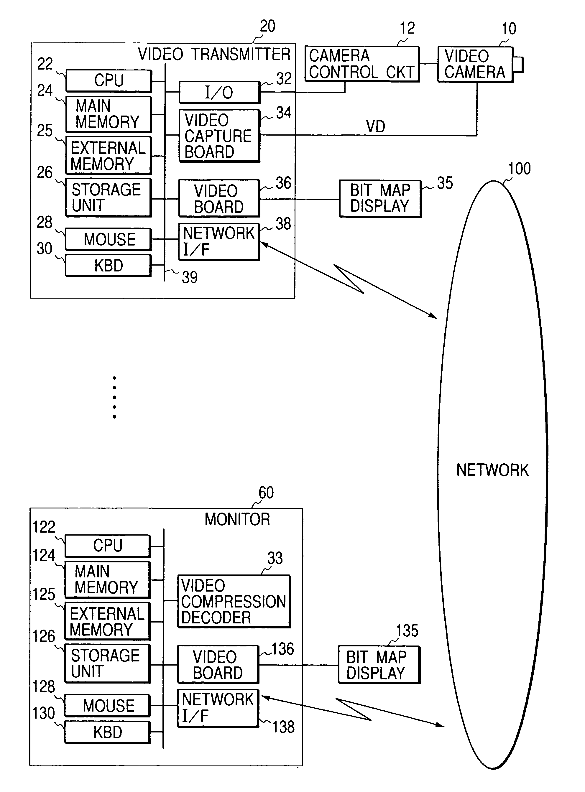
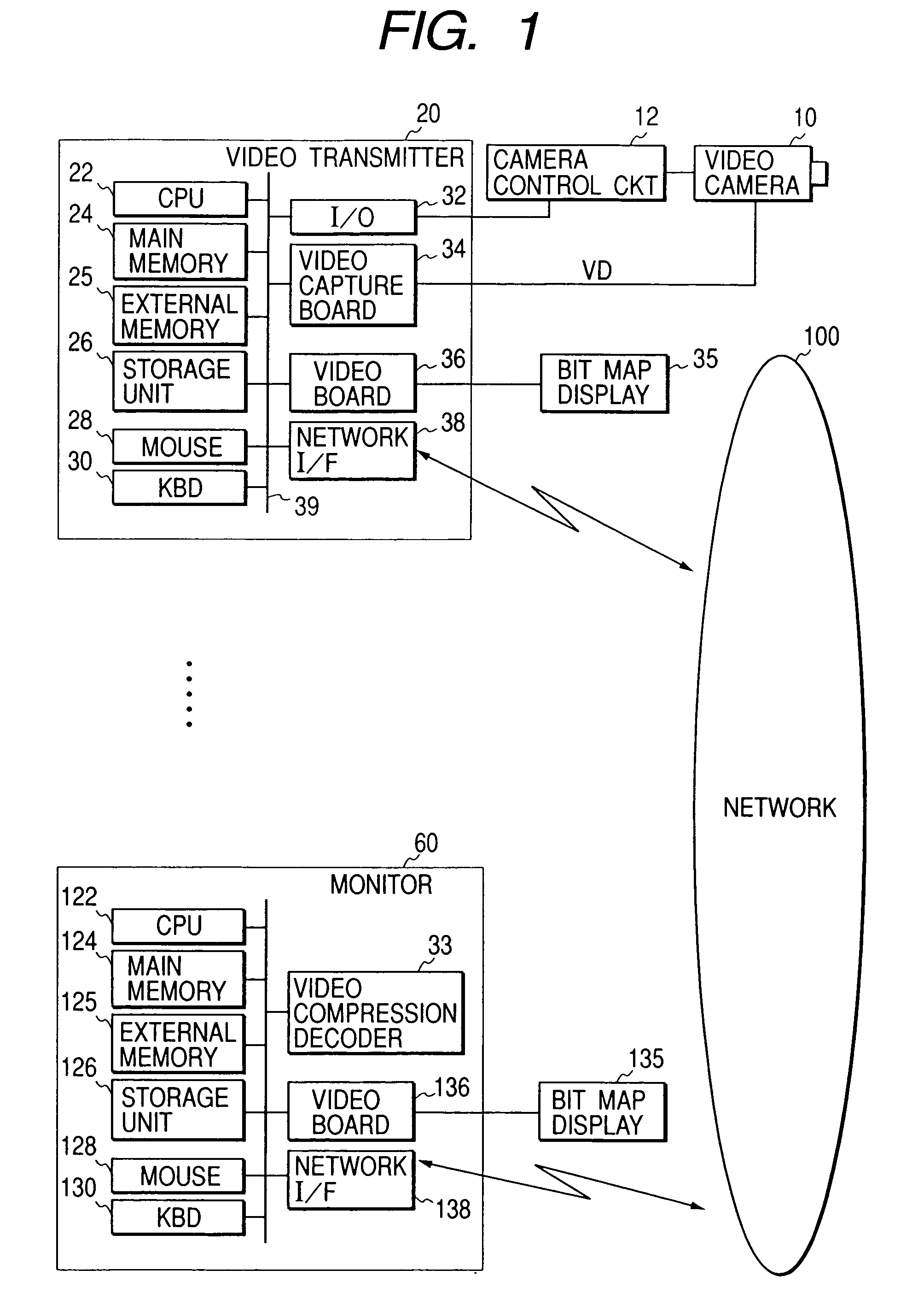
[0053]FIG. 1 is a block diagram showing the overall structure of a communication system including a video communication system according to one embodiment of the present invention.

[0054]In FIG. 1, numeral 10 denotes a video camera which generates video (or an image signal) on the basis of a taken (captured) image. Numeral 20 denotes a video transmitter such as a work station (WS), a personal computer (PC) or the like which transmits the image signal from the video camera 10 to a monitor 60 and receives a control signal from the monitor 60 to control the video camera 10. Numeral 60 denotes a monitor, such as a WS, a PC or the like, which receives an image signal from the video transmitter 20 and transmits a control signal to the video transmitter 20 to control the video camera 10.

[0055]Plural video transmitters 20 and plural monitors 60 can communicate with each other through a network 100. Preferably, the video transmitter analog-to-digital (A / D) converts the image signal from the v...

second embodiment

FIGS. 28 and 29

[0160]In the first embodiment, the camera state is notified to the video reception software at a timing when the camera state is notified from the camera control server software. However, in the second embodiment, the camera state is notified to the video reception software after a predetermined time period elapses.

[0161]FIGS. 28 and 29 are flow charts showing operation of the map management server software. It should be noted that the operations of other software in the second embodiment are substantially the same as those in the first embodiment.

[0162]The changed parts (i.e., parts different from those of the first embodiment) in the flow charts are as follows.

[0163]In steps S740 and S742, if the camera state is notified from the camera control server software, the camera information of the video camera concerned is updated.

[0164]In steps S770 and S772, when the previously set (predetermined) time period elapses, the camera information of all the video cameras is no...

third embodiment

FIGS. 30, 31 and 32

[0165]In the first embodiment, the map management server software notifies the camera state to the video reception software. However, in the third embodiment, the video reception software inquires of the map management server software as to the camera state every time a predetermined time period elapses.

[0166]FIG. 30 shows the operation flow of the third embodiment which is different from that of the first embodiment.

[0167]The changed parts (i.e., parts different from those of the first embodiment) in the flow charts are as follows. It should be noted that the operations of other software in the third embodiment are substantially the same as those in the first embodiment.

[0168]In steps S290 and S291, instead of the processing in which the camera state notification is checked from the map management server software, a map state request is notified to the map management server software every time a predetermined time period elapses, and the video reception software ...


PUM


Abstract

In a system wherein one or more controllable camera(s) and one or more monitor(s) for displaying video information received from the camera(s) are connected to each other through a communication device, the states of all the cameras can be always understood at any monitor. Map management server software is provided to receive notification(s) of camera state information by all the cameras with the predetermined device, and to transmit the camera state information to all the monitors.

Description

BACKGROUND OF THE INVENTION[0001]1. Field of the Invention[0002]The present invention relates to a communication apparatus, a storage medium, a camera and a processing method.[0003]2. Related Background Art[0004]A video transmission system has been proposed in which, for example, plural video cameras and computers are located inside a building, and these video cameras and the computers are networked through communication lines, thereby realizing video transmission among plural desired points and interactive communication by video and audio.[0005]In this video transmission system, a user of the computer at one point (local computer) can remote-control the video camera at a desired remote point and display the video taken by the remote-controlled video camera on the screen of the user's local computer.[0006]Further, in a video transmission system capable of remote-controlling a remote video camera, especially, as the number of the video cameras to be remote-controlled increases, it is...

Claims


Application Information

Patent Timeline
IPC IPC(8): H04N7/173H04N21/218H04N7/18H04N21/442H04N21/6587
CPCH04N7/181H04N21/21805H04N21/44222H04N21/6587H04N21/44224
Inventor YONEZAWA, HIROKINAKAMURA, YASUOTANAKA, KOICHIRO
Owner CANON KK
Features
  • Generate Ideas
  • Intellectual Property
  • Life Sciences
  • Materials
  • Tech Scout
  • Unparalleled Data Quality
  • Higher Quality Content
  • 60% Fewer Hallucinations
Learn More