

Collapsible tube with a distributor head without air return
a distributor head and collapsible tube technology, which is applied in the direction of packaging, containers preventing decay, flexible containers, etc., can solve the problems of mediocre delivery ratio of tubes equipped with such pumps, particularly tight leakage of pump attachments, and relatively expensive tubes made according to fr 2 630 998
Inactive Publication Date: 2007-05-29
CEBAL SA
View PDF6 Cites 14 Cited by
- Summary
- Abstract
- Description
- Claims
- Application Information
AI Technical Summary
Benefits of technology
[0002]The invention relates to collapsible tubes for storing and distributing liquid to pasty products keeping them protected from ambient air. These tubes are fitted with non-return pumps or valves to prevent pollution from ambient air, firstly by preventing product that has been expelled from the port from returning inside the tube, and secondly by preventing air from entering due to relaxation of the pressure on the pump or the skirt.
Problems solved by technology
The pump attachment is particularly leak tight due to the fact that the flange is embedded in the moulded cap.
The tube head made according to FR 2 630 998 is fairly expensive, particularly due to the quality of the pump associated with this head.
Furthermore, the tube equipped with such a pump has a mediocre delivery ratio due to the large diameter of the rigid cap into which the flange of the pump is embedded.
Furthermore, at the end of use it is observed that it is more and more difficult to fix the capsule that protects the diffuser connected to the pump because the periphery of the shoulder that acts as a housing at the bottom of the capsule is deformed.
Although the problem of deformation of the skirt and the shoulder has been solved, there are still moulding difficulties related to differences in thickness between the thin helical elastic arms supporting the sealing means and the remainder of the head.
Furthermore, this type of tube cannot be manufactured at high production rates under satisfactory economic conditions.
The valve described in U.S. Pat. No. 3,438,554 is difficult to insert in the neck since the elastic flared head has to be deformed in the radial direction so that the neck and the inside of the central part of the shoulder can be trapped between this elastic head and the rigid ring.
Apart from these difficult assembly problems when manufacturing at high production rates, this valve has a number of disadvantages in use; since the head has been predeformed so that it can be inserted in the neck, it does not always perfectly return to its initial shape, so that it does not make a sealed contact in its valve seating; moreover, the head comes out of the tube during use which weakens it.
Finally, it always forms an obstacle in front of the port, with the result that the flow of extruded product that comes is not well controlled, either in terms of the distributed flow rate or the direction of the jet.
Finally, there are several disadvantages with the tube head disclosed in U.S. Pat. No. 4,635,826.
Firstly, the disk with limited axial displacement does not always return to its closed position.
Then, the head thus equipped with its valve is incapable of providing good product delivery ratios.
Finally, although the assembly composed of the wall of the ring support and the wall of the neck is rigid enough to prevent the product contained in the cylindrical cavity that they surround from being emptied, they are still easily deformable and consequently make the attachment less reliable and less leak tight than what was originally required.
Click fit beads with a large radial height (typically more than one millimetre) have to be formed to hold the valve in position inside the neck, but these beads form relief that is firstly difficult to remove from the mould, and secondly is easily damaged when the valve is inserted inside the neck.
Method used
View moreImage
Smart ImageViewing Examples

Examples
first embodiment
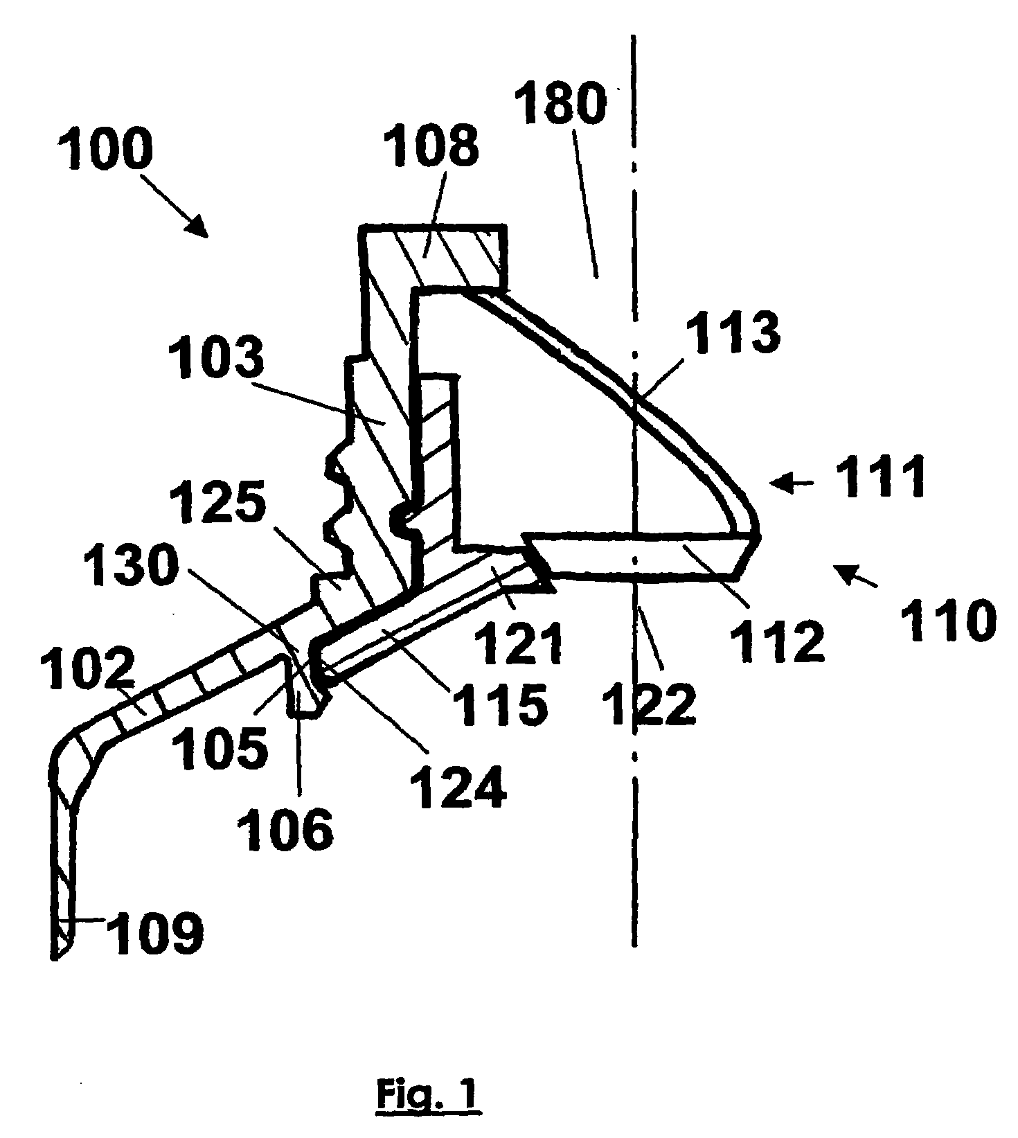
[0040]FIG. 1 illustrates a partial half-section along a diameter of a particular tube head according to the invention corresponding to the The sealing means and its elastic support element are not shown in section.
second embodiment
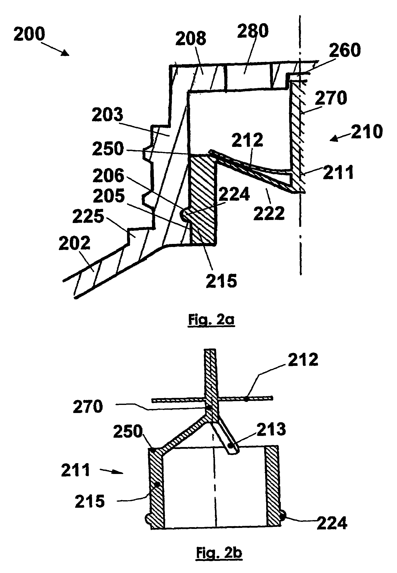
[0041]FIG. 2a illustrates a half-section along a diameter of a particular tube head according to the invention corresponding to the FIG. 2b shows the single piece valve after moulding and before being inserted in the neck.
third embodiment
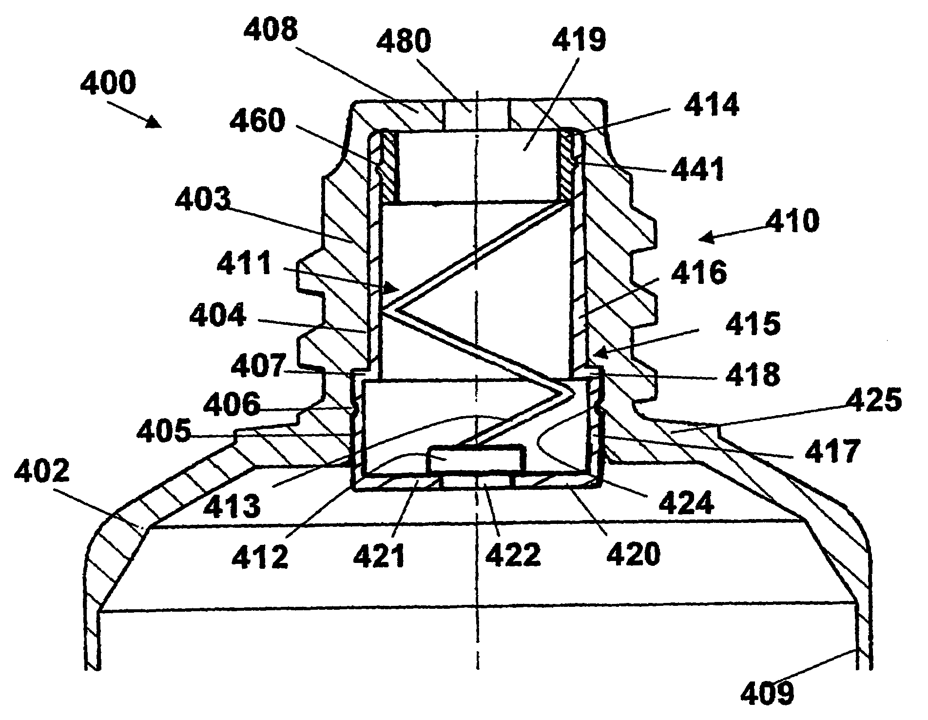
[0042]FIG. 3 illustrates a half-section along a diameter of a particular tube head according to the invention corresponding to the
Login to View More PUM
 Abstract
Collapsible tube head (100, 200, 300, 400) comprising a neck (103, 203, 303, 403) which is fitted, with a port (180, 280, 380, 480) and a shoulder (102, 202, 302, 402). The aforementioned head is fitted with a valve (110, 210, 310, 410) which is inserted in the neck of the said collapsible tube, the said valve comprising a sealing means (112, 212, 312, 412) which is connected to a ring support (115, 215, 315, 415) having an opening (122, 222, 322, 422), the said sealing means being maintained in the closed position of the said opening when the tube is not compressed, and being maintained in the open position when the tube is compressed. The inner surface of the tube is provided with a bore (105, 205, 305, 405) which is disposed close to the base of the said neck. The ring support is fixed to the bore by means of bonding, soldering or force fitting, and the said bore and ring support are preferably provided with complementary connection means, in particular a groove and rice grains.
Description
[0001]This application is a filing under 35 USC 371 of PCT / FR02 / 02877 filed Aug. 14, 2002.TECHNICAL DOMAIN[0002]The invention relates to collapsible tubes for storing and distributing liquid to pasty products keeping them protected from ambient air. These tubes are fitted with non-return pumps or valves to prevent pollution from ambient air, firstly by preventing product that has been expelled from the port from returning inside the tube, and secondly by preventing air from entering due to relaxation of the pressure on the pump or the skirt.STATE OF THE ART[0003]Application FR 2 630 998 deposited by the Applicant discloses a tube comprising a skirt and a head equipped with a distribution pump provided with an annular flange. This head is fixed on the skirt of the tube and comprises a shoulder connecting the skirt to a plastic cap moulded on the annular pump attachment flange. The nature of the semi-rigid plastic material in the cap is the same as the nature of the surface layers of ...
Claims
Login to View More Application Information
Patent Timeline
 Patent Type & AuthorityPatents(United States)
IPC IPC(8): B65D35/00B65D35/46B65D47/20B65D81/28
CPCB65D35/46B65D47/2075B65D81/28
InventorKERMAN, ERICMOUNIER, LAURESCHNEIDER, BERNARD
OwnerCEBAL SA