Magnetic fishing reel clicker

Inactive Publication Date: 2007-05-29
W C BRADLEY ZEBCO HLDG LLC
View PDF13 Cites 17 Cited by
  • Summary
  • Abstract
  • Description
  • Claims
  • Application Information

AI Technical Summary

Benefits of technology

[0008]The instant invention is directed to an improved clicker mechanism. The clicker mechanism of the invention utilizes magnets that are used to bias the clicker mechanism. When properly located, multiple magnets or multiple magnetic/ferrous pieces can provide an appropriate attracting and/or opposing force on each other that will create a force sufficient to bias the clicker mechanism.
[0009]An example clicker assembly utilizes two (2) magnets to actuate the clicker mechanism. A first sub-assembly is secured tightly to a spool. A second sub-assembly pivots about a post that is spaced an appropriate distance away from the spool. Each sub-assembly is provid

Problems solved by technology

Consequently, some components may experience corrosion that may reduce the effectiveness of the component.
One component in particular that is susceptible to corrosion is the clicker mechanism.
A difficulty associated with conventional springs i

Method used


Image

  • Magnetic fishing reel clicker
  • Magnetic fishing reel clicker
  • Magnetic fishing reel clicker

Examples


Embodiment Construction

[0017]Before explaining the present invention in detail, it is important to understand that the invention is not limited in its application to the details of the embodiments and steps described herein. The invention is capable of other embodiments and of being practiced or carried out in a variety of ways. It is to be understood that the phraseology and terminology employed herein is for the purpose of description and not of limitation.

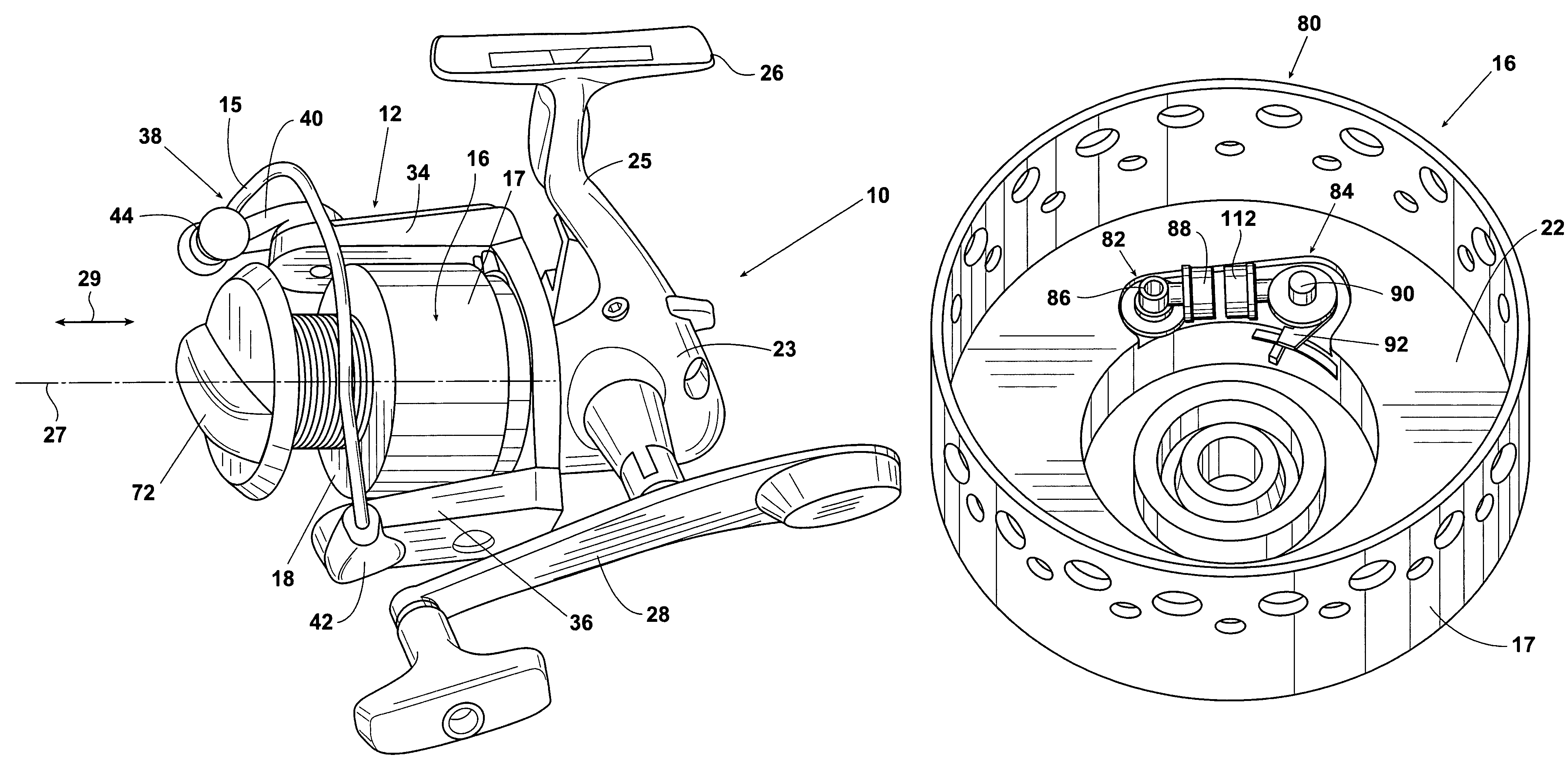
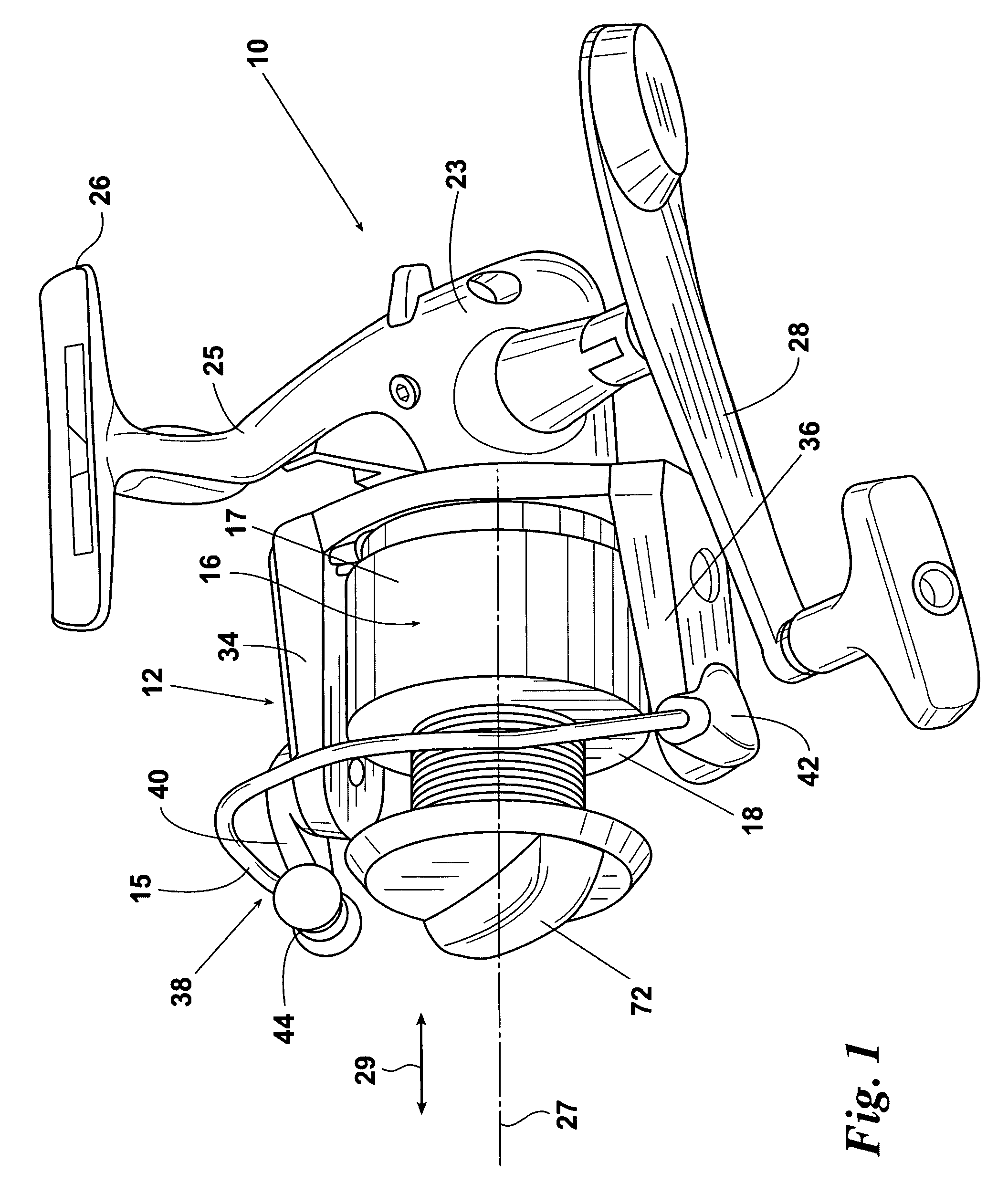
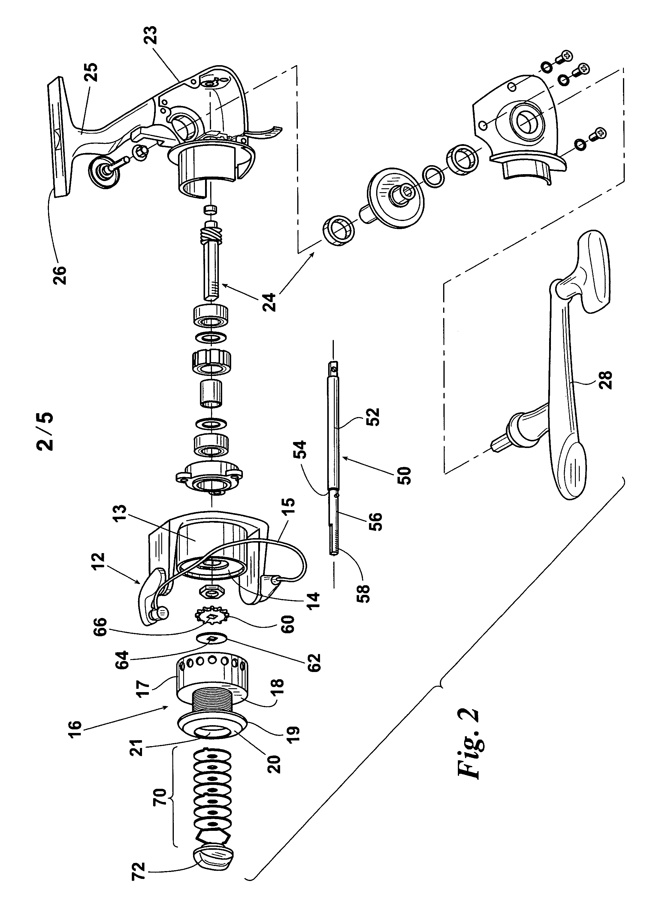
[0018]Referring now to FIG. 1, a spinning-type fishing reel, according to the present invention, is designated generally as 10. Spinning reel 10 has a rotor 12. Rotor 12 has a generally cylindrical rotor body 13 (FIG. 2), which defines a rotor face 14 (FIGS. 2 and 3). Bail wire 15 is provided to wrap a supply of line around spool 16 at the front of reel 10. Spool 16 defines a skirt 17, a spool shoulder 18, a spool lip 19 (FIG. 2), a spool cap 20 (FIG. 2), spool cap cavity 21 (FIG. 2), and spool face 22 (FIG. 4). It should be understood that reel 10 de...


PUM


Abstract

A clicker mechanism for a fishing reel is described. A typical fishing reel has a spool defining an orifice and a shaft passing through the orifice. A component having an irregular surface, such as a gear-like component with teeth or a ring defining a serrated inner surface engages the shaft. A clicker assembly may be affixed to the spool. The clicker assembly includes a clicker for engaging the clicker gear. The clicker alternately moves from a first position to a second position. The clicker assembly utilizes a magnet that provides a magnetic force to return the clicker to the first position from the second position. Two magnets may be used to exert magnetic force against one another, either with an attracting or a repelling force.

Description

FIELD OF THE INVENTION[0001]This invention relates generally to the use of magnetic force to actuate or locate a clicker mechanism.BACKGROUND OF THE INVENTION[0002]Various types of fishing reels are known in the art. An example of a common fishing reel is a spinning reel. A typical spinning reel has a body having a mounting structure extending from the top of the body for mounting the reel beneath a fishing rod. A pinion sleeve is rotatably mounted through a front end of the body. A rotor assembly is secured to a forward end of the pinion sleeve. A main shaft slidably extends through the pinion sleeve and through the rotor assembly. A line spool is secured on a forward end of the main shaft. A bail wire assembly is attached to the rotor assembly for grasping a fishing line to facilitate winding of the line around a line spool. A drive shaft extends laterally into the side of the body structure. A crank handle is secured on the exterior end of the drive shaft. A drive gear (e.g., a f...

Claims


Application Information

Patent Timeline
IPC IPC(8): A01K89/02
CPCA01K89/01A01K89/0111A01K89/027
Inventor LITTAU, CHRISTOPHER S.DENTON, JOSHUA M.
Owner W C BRADLEY ZEBCO HLDG LLC
Why Eureka
Try Eureka