Blind rivet nut

a blind rivet and nut technology, applied in the direction of screws, dowels, fastening means, etc., can solve the problem of no longer being able to have uniform contact with the flange of the blind rivet nut, and achieve the effect of reducing the load in the area of the deformation bulge, reducing the load, and being easy to suppor

Inactive Publication Date: 2007-05-29
NEWFREY
View PDF30 Cites 26 Cited by
  • Summary
  • Abstract
  • Description
  • Claims
  • Application Information

AI Technical Summary

Benefits of technology

[0008]According to a further aspect of the invention, the flange of the blind rivet nut has a diameter corresponding to at least double the least outside diameter of the deformable region. As a result, the sheet-metal or other part supporting the blind rivet nut is supported by the flange in a large area around the attachment, and any deformation of the contact area is opposed. Besides, tilting forces acting on the blind rivet nut are more readily supported, reducing the load in the area of the deformation bulge.
[0009]The blind rivet nut, according to a further aspect of the invention, may be made of steel by cold forming using the flow pressure process. This highly economical method of production has the per se that the material is consolidated by the transformation, so that setting of the blind rivet nut requires higher deformation stresses and leads to a more intense loading of the sheet metal or other thin-walled part. Here the measurement of the wall thickness of the deformable region according to the invention represents a favorable compromise, since owing to the comparatively small wall thickness, the forces of deformation can be kept small, while on the other hand the cross section of the deformable region is still of adequate size so that the blind rivet nut can be produced by the flow pressure process. In the interaction of these measures, then, a blind rivet nut is created that satisfies installation and use requirements and furthermore can be produced especially economically.

Problems solved by technology

In fastening blind rivet nuts of the specified kind, the problem arises that the forces acting on the thin-walled or sheet-metal part accommodating the blind rivet nut may deform the sheet-metal or other thin-walled part in such manner that uniform contact with the flange of the blind rivet nut is no longer obtainable.
This is especially disadvantageous if a tight connection, preventing passage of a liquid or gaseous medium, is to be made between the blind rivet nut and the sheet-metal or other thin-walled part.
Another problem arises in the fastening of the blind rivet nut, in achieving a sufficiently great radial extent of the polygonal bulge formed in the deformation of the deformable region on the blind side.

Method used


Image

  • Blind rivet nut
  • Blind rivet nut

Examples


Embodiment Construction

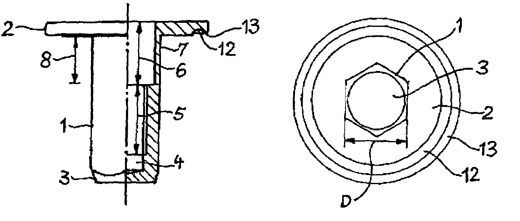
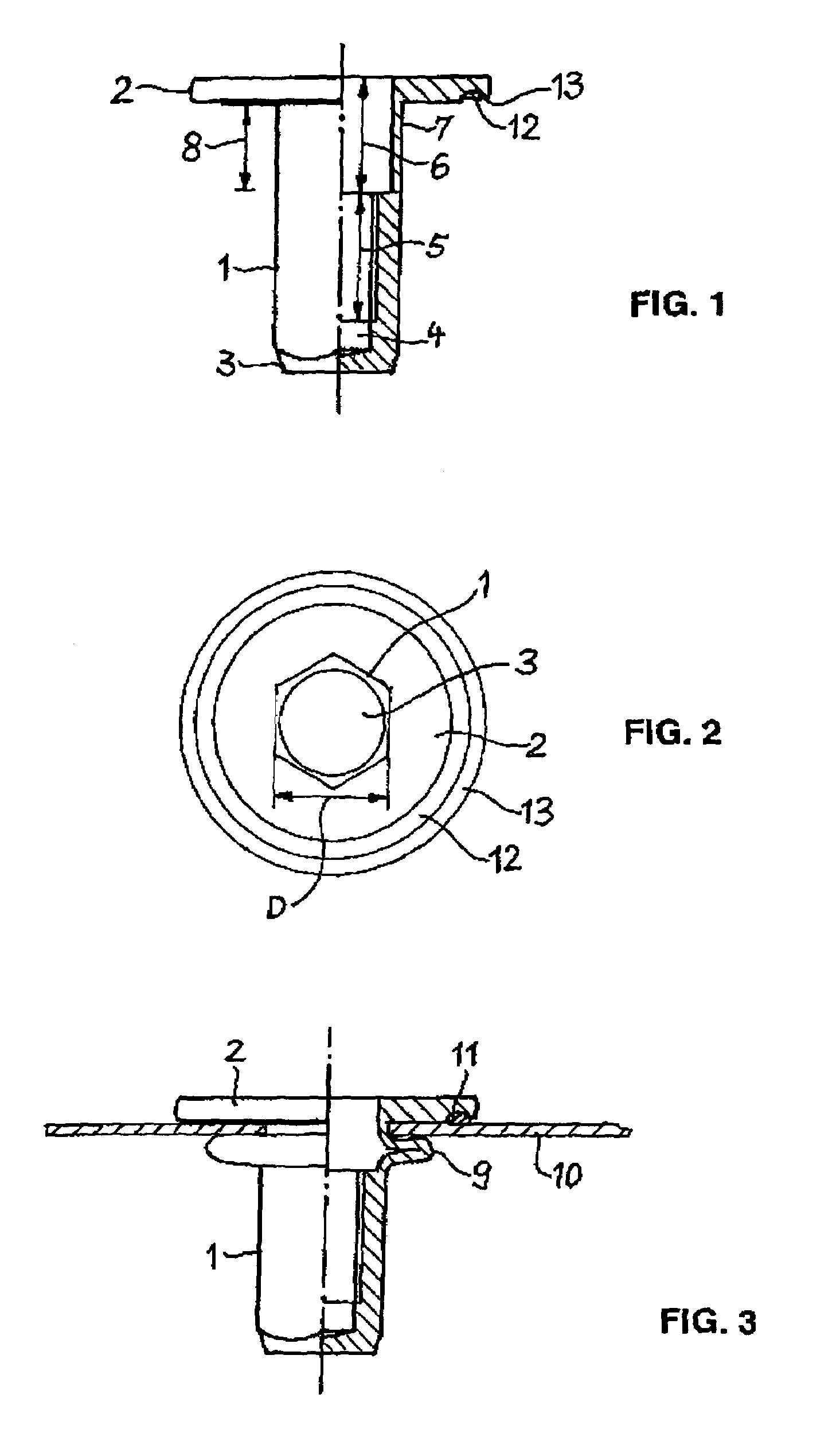
[0014]The blind rivet nut represented in the drawing has an elongated shank 1, bearing a flange 2 at one end. The shank 1 has the shape of a regular hexagonal prism, and is conically pointed at its end opposed to the flange 2. Owing to the hexagonal outer contour, when the shank is placed in a suitably shaped bore adapted in size to the cross-section of the shank, rotation of the shank in the bore is prevented. The pointed end facilitates introduction of the shank into the bore. The flange 2 extends at right angles to the lengthwise axis of the shank 1 and has the shape of a plane circular disk. Alternatively, the flange may have a polygonal shape, for example, square or hexagonal.

[0015]Through the flange 2 and the greater part of the length of the shank 1, a bore 4 extends, whose lengthwise axis coincides with the lengthwise axis of the shank 1. The bore 4 is closed at the end 3 of the shank 1. It comprises a first bore segment 5 adjacent to the end 3, provided with an internal thr...


PUM


Abstract

A blind rivet nut has a head configured as an annular flange and a shank comprising a head end, a foot end and a cylindrical bore closed at the foot end of the shank and extending from the head end to the foot end in lengthwise direction, and a second bore segment near the head end whose diameter is greater than the diameter of the first bore segment. The wall surrounding the second bore segment forms a plastically deformable region of the shank, and has an outer surface with the shape of a regular polygonal, in particular hexagonal, prism. To achieve a uniform and tightly sealing contact of the flange with the part accommodating the blind rivet nut, the wall thickness of the deformable region in the thinnest places is 4% to 6% of the least outside diameter of the deformable region.

Description

CROSS-REFERENCE TO RELATED APPLICATIONS[0001]This application claims the benefit of German Patent Application No. 10 2004 003 240.8 filed Jan. 21, 2004. The disclosure of the above application is incorporated herein by reference.BACKGROUND OF THE INVENTION[0002]The invention relates to a blind rivet nut having a head forming an annular flange and a shank comprising a head end, a foot end, and a cylindrical bore extending in lengthwise direction from the head end to the foot end, closed at the foot end of the shank and having a second bore segment neighboring the head end whose diameter is greater than the diameter of the first bore segment, the wall surrounding the second bore segment forming a plastically deformable portion of the shank and having an outer surface formed as a regular polygon, in particular a hexagonal prism.[0003]Blind rivet nuts are employed chiefly in thin-walled parts, in particular made of sheet metal, to provide them with a fastening thread that can serve for ...

Claims


Application Information

Patent Timeline
Patent Type & Authority Patents(United States)
IPC IPC(8): F16B19/10F16B19/00F16B33/00F16B37/06
CPCF16B37/067F16B19/1045F16B33/002
Inventor SCHNEIDER, STEFAN
Owner NEWFREY
Why Eureka
Try Eureka