Plug device with a plug adapter

a plug adapter and plug device technology, applied in the direction of coupling device connection, electric discharge tube, electrical apparatus, etc., can solve the problems of comparatively large space, comparatively high cost, and complex manufacturing of plug devices, and achieve the effect of simple and convenient operation

Active Publication Date: 2007-05-29
HELMS MAN IND
View PDF15 Cites 26 Cited by
  • Summary
  • Abstract
  • Description
  • Claims
  • Application Information

AI Technical Summary

Benefits of technology

[0005]One object of the invention is accordingly to design a plug device of the type initially mentioned to have a simple and readily operated adaptation to different country specific line sockets.
[0007]The plug adapter is able to be simply mounted on the base part and owing to the locking by means of the locking means constitutes a compact structural unit reliably connected with the base part. Following unlocking of the locking means the plug adapter may be removed readily from the base part. Then it is possible to attach a different plug adapter suitable for other country specific conditions to the base part. A plug device in accordance with the invention may have a plurality of country specific plug adapters so that an adaptation of the plug device to country specific line sockets is readily possible without any complications.
[0010]The following measure contributes to the mechanical coherence of the combination comprising the base part and the plug adapter. The plug adapter is in the mounted state essentially not able to be tilted athwart the direction of insertion. This is for example made possible if the plug adapter is fitted deeply into the plug socket and / or ample engagement faces are present for the plug adapter within the line socket and / or at its edge regions. Moreover, guide means, to be explained in the following are provided contributing to providing stability as regards tilting. The locking means for locking the plug adapter must also, in this form of the invention, act essentially oppositely to the insertion direction, while on the contrary a stabilization athwart the insertion direction is less important. The mechanical load on the locking means is reduced as a result. The locking means may be designed to be compact and / or readily operated.
[0011]The locking means advantageously has at least one detent projection for fitting into a detent socket. The detent projection may for example be arranged on the plug adapter and the detent socket may be arranged on the base part or the other way round. The detent projection and / or a detent socket may be arranged on a resilient actuating element. By actuation of the actuating element the detent projection and the cooperating detent socket are disengaged so that the plug adapter is able to be detached from the base part. On plugging the plug adapter to the base part the resilient actuating element is advantageously automatically disengaged in order, on arriving in the mounted state, automatically spring back so that the detent projection and the detent socket engage again. The actuating element conveniently projects, at least partly, during non-operation past the outer face of the base part and / or the plug adapter. By pressing on the actuating element so that it advantageously essentially moves behind the outer face of the base part or, respectively, of the plug adapter, the plug adapter is unlocked. It is an advantage for the actuating stroke of the actuating element to be so large that accidental operation is prevented.
[0013]For the electrical connection of the plug socket with the base part it is an advantage to have electrical plug contacts at the plug socket of the base part, such contacts not projecting past the plug socket and fitting into the plug receiving sockets of the plug adapter in the mounted condition. Accordingly the plug contacts are protected from mechanical damage.

Problems solved by technology

The known combination of a base part and a plug adapter requires, owing to the plugging together of a plurality of country specific plug-socket combinations, a comparatively large amount of space.
Another set of problems arises for the manufacture of plug devices.
The manufacture of different plug devices is however complex and comparatively expensive, more particularly in the case of small batches.

Method used


Image

  • Plug device with a plug adapter
  • Plug device with a plug adapter
  • Plug device with a plug adapter

Examples


Embodiment Construction

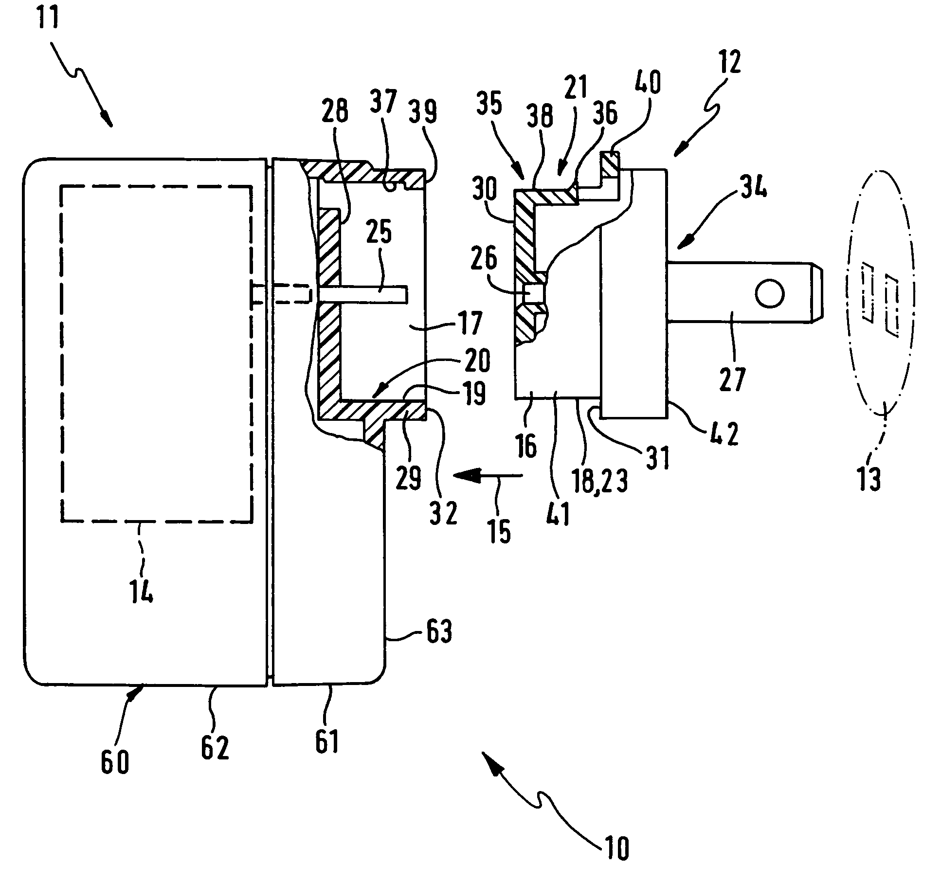
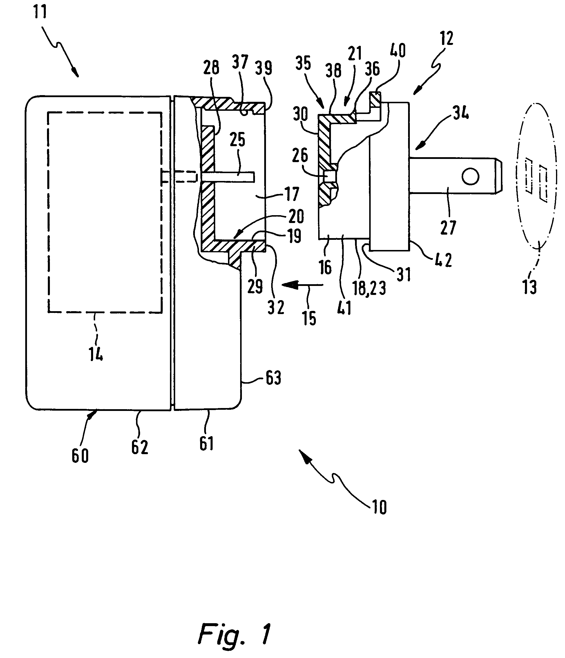
[0018]In the case of the plug device 10 illustrated in FIG. 1 a country specific electrical plug adapter 12 is able to be joined by plugging with a base part 11 so that the plug device may be plugged into a country specific electrical plug receiving wall socket 13. The base part 11 can comprise an electrical device 14, as for example an electric lamp, a power pack, a charging device for accumulators or the like. The electrical device 14 may be for example a transformer, an inverter, a rectifier or some electrical adaptation means. The electrical device 14 may operate linearly or with a switching effect. The plug device 10 or respectively the base part 11 are in the present case portable. However in principle designs for stationary and non-portable applications are possible.

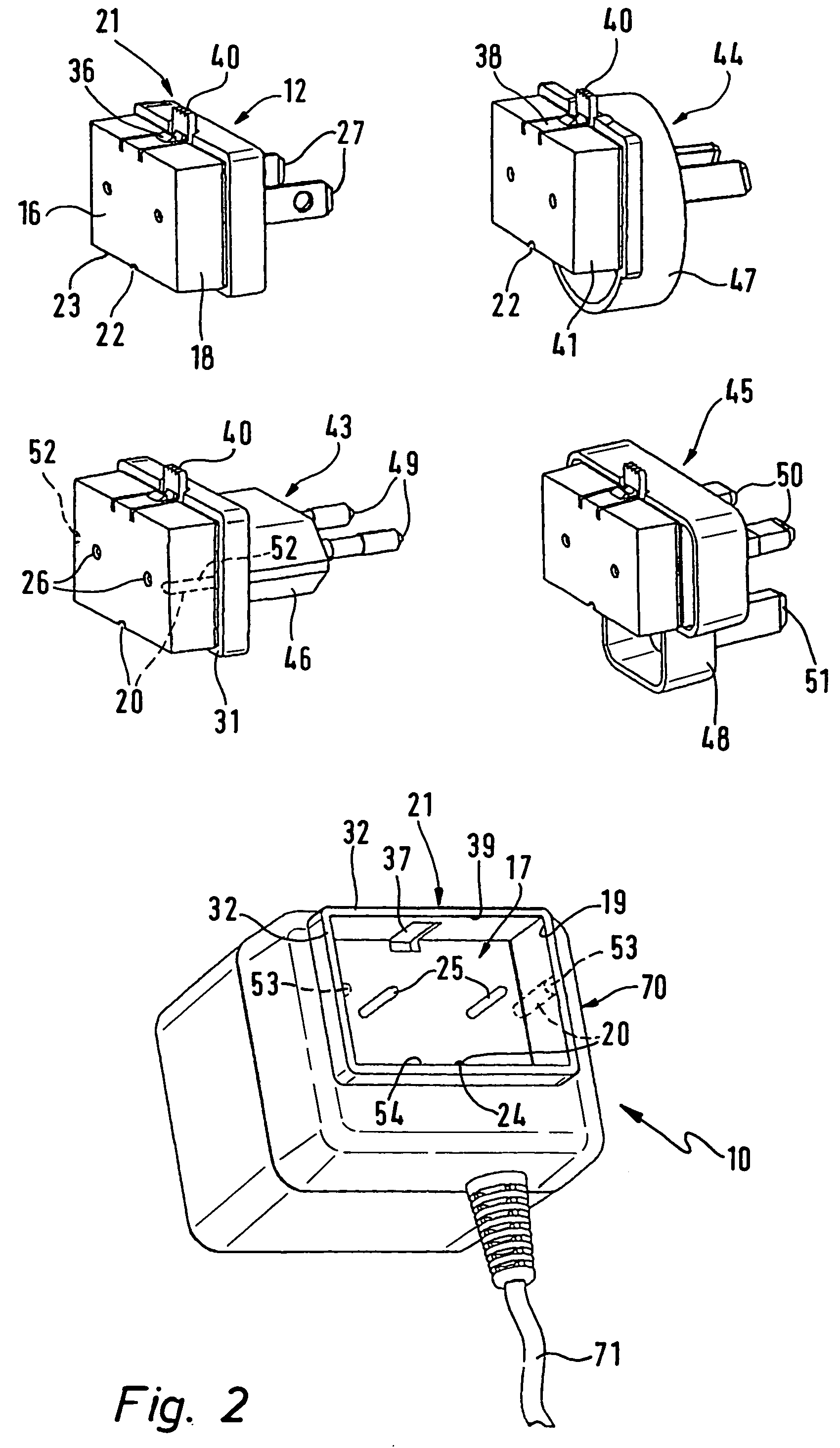
[0019]On the front top region of the base part 11 a plug socket 17 is arranged, into which the plug adapter 12 is able to be plugged. The base part 11 has a housing 60, for example of plastic, with a front and rea...


PUM


Abstract

A plug device for fitting into a country specific electrical wall socket comprises a base part and at least one country specific electrical plug adapter, able to be secured to the base part, for fitting into the country specific line socket. The at least one plug adapter may be locked without using tools in an assembled state with a locking means and released from the base part after unlocking the locking means.

Description

BACKGROUND OF THE INVENTION[0001]The invention relates to a plug device for plugging into a country specific electrical plug receiving socket comprising a base part and at least one country specific electrical plug adapter, adapted to be secured to the base part, for insertion of the plug device into the country specific line socket.THE PRIOR ART[0002]In the case of base part it is for example a question of a power supply adapter or the like, which by means of the country specific electrical plug adapter may be connected with distinct country specific line socket outlets, which for instance are different in the USA, in Europe, in Australia or in the United Kingdom. The known country specific plug adapters have country specific characteristics both on the input side and also on the output side: for example a plug adapter for use in the USA may have a base part with a European plug plugged into it in order to provide adaptation to a line socket in the USA. Alternatively for example a ...

Claims


Application Information

Patent Timeline
Patent Type & Authority Patents(United States)
IPC IPC(8): H01R25/00H01R13/66H01R31/06
CPCH01R31/06H01R13/6666
Inventor NG, YUK HUNG
Owner HELMS MAN IND
Why Eureka
Try Eureka