Blood removal system

a blood removal system and blood technology, applied in the field of blood removal systems, can solve the problems of inconvenient use, large pain in the puncture, and relatively wide housing shape, and achieve the effect of reducing friction and fewer components

Active Publication Date: 2007-05-29
ROCHE DIABETES CARE INC
View PDF123 Cites 74 Cited by
  • Summary
  • Abstract
  • Description
  • Claims
  • Application Information

AI Technical Summary

Problems solved by technology

However, the puncture is connected with substantial pain.
These types of blood removal system were, however, not suitable to meet the high demands required when a routine monitoring of analytical values of blood is necessary.
It requires, however, a relatively wide housing shape, which is considered less favorable by many users.

Method used


Image

  • Blood removal system
  • Blood removal system
  • Blood removal system

Examples


Embodiment Construction

[0028]The embodiments described below are merely exemplary and are not intended to limit the invention to the precise forms disclosed. Instead, the embodiments were selected for description to enable one of ordinary skill in the art to practice the invention.

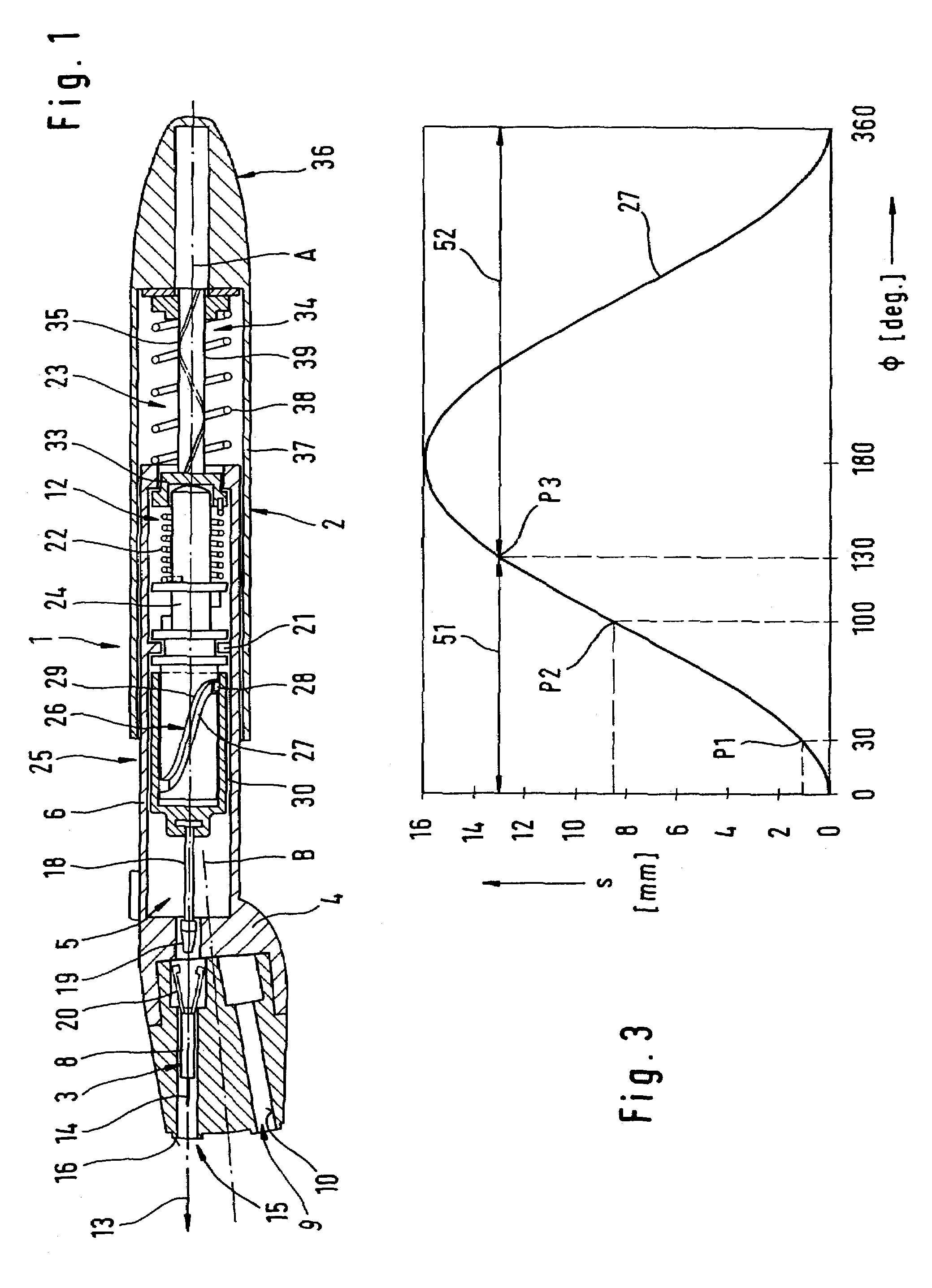
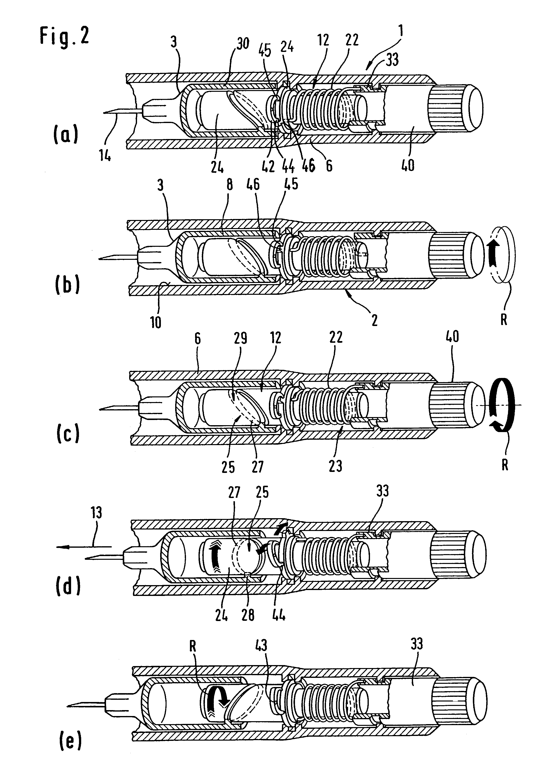
[0029]The blood removal system 1 shown in FIG. 1 comprises a puncture apparatus 2 and lancets 3. In the shown embodiment the lancets 3 are held in a revolver head 4 which can be attached exchangeably on the forward end 5 of the puncture apparatus 2 as part of its housing 6.

[0030]The revolver head 4 is rotatable about an axis of rotation B to be positioned in a plurality of positions, in which, respectively, one lancet 3 is arranged coaxial with the main axis A of the puncture apparatus 2. The lancet bodies 8 and the recesses 9, in which the lancets 3 sit, are shaped relative to one another such that the walls of the recesses 9 form lancet guides 10, by means of which the respective lancet 3 is guided on a predetermined puncture ...


PUM


Abstract

Blood removal system for removing blood for diagnostic purposes including a housing, a lancet guide, and a lancet drive with a drive spring. The lancet drive comprises a cocking device, in order to tension the drive spring, a drive rotor that is driven by the drive spring, and an output-side coupling mechanism, by means of which the rotational movement of the drive rotor is converted into the puncturing movement.

Description

FIELD OF THE INVENTION[0001]The invention refers to a blood removal system for withdrawing blood for diagnostic purposes.BACKGROUND OF THE INVENTION[0002]In order to withdraw a minimal amount of blood from body parts (generally, a finger or an ear lobe) for analytical-diagnostic purposes, lancets are used, which are pricked into the corresponding body part for producing a wound. Because this procedure is manually performed, specially trained personnel are necessary. However, the puncture is connected with substantial pain.[0003]Blood removal systems which comprise a pricking apparatus and associated lancets, specially adapted to the lancets, have also been used. In a housing of the pricking apparatus, a lancet drive is located, by means of which a lancet is mechanically stuck into the skin. A spring serves as a driving element for the puncturing movement. At the beginning of the development, very simple constructions were used, in which the lancet was directly attached to an end of ...

Claims


Application Information

Patent Timeline
Patent Type & Authority Patents(United States)
IPC IPC(8): A61B17/32A61B5/151A61B5/15A61B5/155
CPCA61B5/1411A61B5/15157A61B5/150022A61B5/15113A61B5/15117A61B5/15151A61B5/150259A61B5/150412A61B5/150503A61B5/150824A61B5/1519A61B5/15194
Inventor LIST, HANSRUSCHKE, PETERTHOES, BRUNO ROBERTKINTZIG, HANSSCHABBACH, MICHAEL
Owner ROCHE DIABETES CARE INC
Why Eureka
Try Eureka