Operating apparatus and an electric instrument

a technology of operating apparatus and electric instrument, which is applied in the direction of electrical apparatus, piezoelectric/electrostrictive/magnetostrictive devices, piezoelectric/electrostriction/magnetostriction machines, etc., can solve the problem of large and achieve the effect of reducing the size of the entire apparatus

Active Publication Date: 2007-05-29
SEIKO EPSON CORP
View PDF9 Cites 63 Cited by
  • Summary
  • Abstract
  • Description
  • Claims
  • Application Information

AI Technical Summary

Benefits of technology

[0005]It is an object of the present invention to provide an operating apparat

Problems solved by technology

However, in conventional operating apparatuses, since a drive mechanism of the driven element is constructed from

Method used


Image

  • Operating apparatus and an electric instrument
  • Operating apparatus and an electric instrument
  • Operating apparatus and an electric instrument

Examples


first embodiment

[0093](First Embodiment)

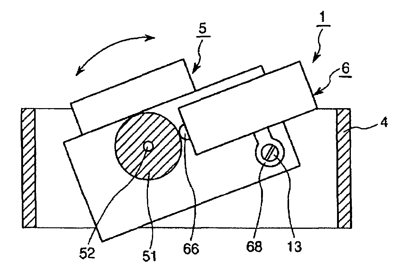
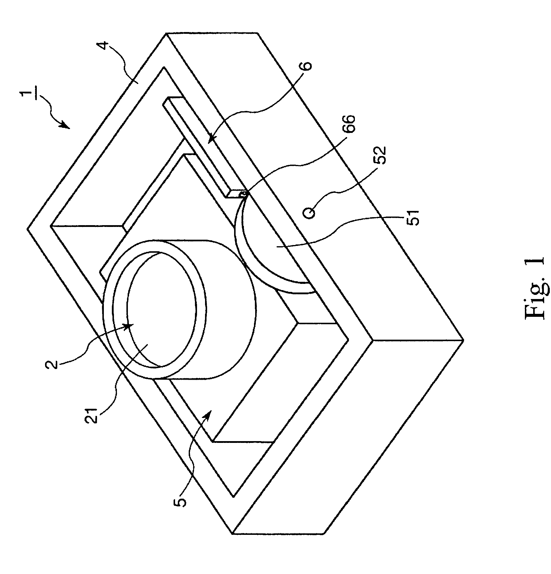
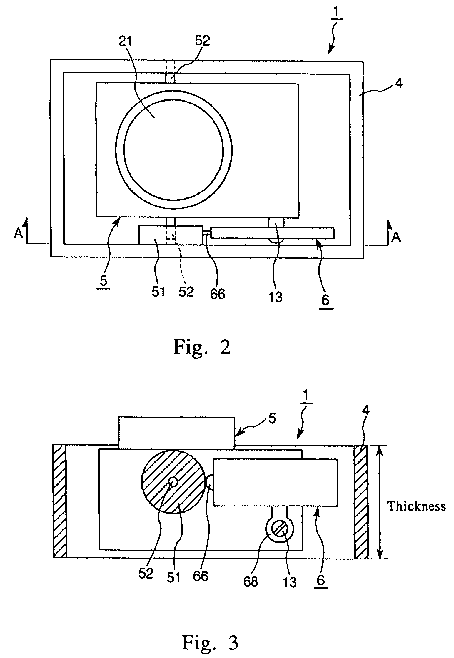
[0094]FIG. 1 is a perspective view illustrating an operating apparatus in a first embodiment according to the present invention. FIG. 2 is a plan view illustrating the operating apparatus shown in FIG. 1. FIG. 3 is a cross-sectional view taken along line B—B of the operating apparatus shown in FIG. 2. FIG. 4 is a cross-sectional view illustrating the optical system and the driven element shown in FIG. 1. The operating apparatus 1 includes an optical system 2, a frame 4, a driven element 5, and a vibrating element 6. The optical system 2 includes a lens 21 and an imaging element (solid imaging element) 22, and serves as an imaging section of the operating apparatus 1. In this regard, the lens 21 may be a pinhole, for example. Further, the imaging element 22 is an image sensor or a charge-coupled device (CCD), for example. The frame 4 is formed from a box frame-shaped member. The operating apparatus 1 is fixedly mounted at a predetermined position of a cradle, ...

second embodiment

[0126](Second Embodiment)

[0127]Next, a description will be given for a second embodiment of the operating apparatus 1.

[0128]FIG. 10 is a perspective view of a vibrating element of an operating apparatus in the second embodiment according to the present invention. FIG. 11 is a block diagram illustrating circuitry of the operating apparatus in the second embodiment according to the present invention.

[0129]Hereinafter, the operating apparatus 1 in the second embodiment will be described, focusing on different points between the above-mentioned first embodiment and the second embodiment. In this regard, explanation of items including the same matters and the like is omitted.

[0130]The operating apparatus 1 in the second embodiment has four modes including a first mode in which a driven element 5 is maintained in a stopping state; a second mode in which the driven element 5 can be rotated (displaced) (i.e., the driven element 5 lies in a free state); a third mode in which the driven eleme...

third embodiment

[0177](Third Embodiment)

[0178]Next, a description will be given for a third embodiment of the operating apparatus according to the present invention.

[0179]FIG. 12 is a perspective view illustrating a vibrating element of the operating apparatus in a third embodiment according to the present invention. Now, in following explanations using FIG. 12, an upper side is referred to as “upper,” a lower side is referred to as “lower,” a right side is referred to as “right,” and a left side is referred to as “left.”

[0180]Hereinafter, an operating apparatus 1 in the third embodiment will be described, focusing on different points between the above-mentioned first or second embodiment and the third embodiment. In this regard, explanation of items including the same matters and the like is omitted.

[0181]The operating apparatus 1 in the third embodiment has characteristics on the point that the operating apparatus 1 can further employ a fifth mode and a sixth mode in which longitudinal vibration ...


PUM


Abstract

An operating apparatus 1 of the present invention has a driven element 5, a frame 4 having a contacted element 51 and rotatably supporting the driven element 5, and an ultrasonic motor. The ultrasonic motor includes a vibrating element 6. The vibrating element 6 includes a first piezoelectric element 62 that undergoes extension and contraction by application of an AC voltage, a reinforcing plate 63 having a contact portion 66 and an arm portion 68, and a second piezoelectric element 64 that undergoes extension and contraction by application of an AC voltage. The first piezoelectric element 62, the reinforcing plate 63, and the second piezoelectric element 64 are laminated in this order. The vibrating element 6 is fixedly mounted on the driven element 5 in a state where the contact portion 66 abuts on the contacted element 51. Further, the vibrating element 6 receives reaction force from the contacted element 51 when the vibrating element 6 vibrates so that the driven element 5 is rotated together with the vibrating element 6 by means of the reaction force.

Description

CROSS REFERENCE TO RELATED APPLICATIONS[0001]This application claims priority to Japanese Patent Application Nos. 2003-100100 filed Apr. 3, 2003 and 2004-020521 filed Jan. 28, 2004, which are hereby expressly incorporated by reference herein in their entireties.TECHNICAL FIELD[0002]The present invention is related to an operating apparatus and an electric instrument.BACKGROUND ART[0003]So far, operating apparatuses that drive a driven element such as a pan-tilt type zoom camera or the like are well known. In such an ultrasonic motor, a technology described in a website (URL: http: / / www.viwemedia. co.jp / kiki / vcc4.htm (Japanese only)) is known as the above-mentioned technology.[0004]However, in conventional operating apparatuses, since a drive mechanism of the driven element is constructed from a large motor such as an electromagnetic motor, there is a problem that the entire apparatus becomes a large size.SUMMARY OF THE INVENTION[0005]It is an object of the present invention to provi...

Claims


Application Information

Patent Timeline
IPC IPC(8): H01L41/08H01L41/09H02N2/00H02N2/06
CPCH02N2/004H02N2/103
Inventor MIYAZAWA, OSAMU
Owner SEIKO EPSON CORP
Why Eureka
Try Eureka