Apparatus and method for generating high-voltage regulation signal in a display

Active Publication Date: 2007-05-29
SAMSUNG ELECTRONICS CO LTD
View PDF7 Cites 4 Cited by
  • Summary
  • Abstract
  • Description
  • Claims
  • Application Information

AI Technical Summary

Benefits of technology

[0011]The present invention provides an apparatus and method for generating a high-voltage regulation signal that protects a switching device, in order to stabilize a regulation voltage of a display and achieve a reduction in costs thereof.

Problems solved by technology

This situation occurs because of a poor high-voltage regulation.
However, in the conventional regulation circuit, an error is detected after an excessive current due to the error already flows to the switching unit 120, and then the voltage signal input to the switching unit 120 is controlled.
Therefore, components constituting the switching unit 120 can be damaged due to the excessive current.
Such a damage of the switching unit adversely affects the control of the regulation voltage, thereby resulting in deterioration of picture quality of the CDT.
Furthermore, the components constituting the switching unit 120 must be frequently replaced, resulting in an increase in cost of the whole system.

Method used


Image

  • Apparatus and method for generating high-voltage regulation signal in a display
  • Apparatus and method for generating high-voltage regulation signal in a display
  • Apparatus and method for generating high-voltage regulation signal in a display

Examples


Embodiment Construction

[0026]Reference will now be made in detail to the embodiments of the present invention, examples of which are illustrated in the accompanying drawings, wherein like reference numerals refer to the like elements throughout. The embodiments are described below to explain the present invention by referring to the figures.

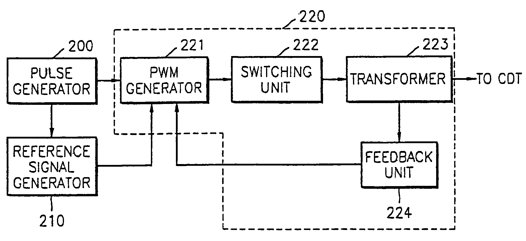
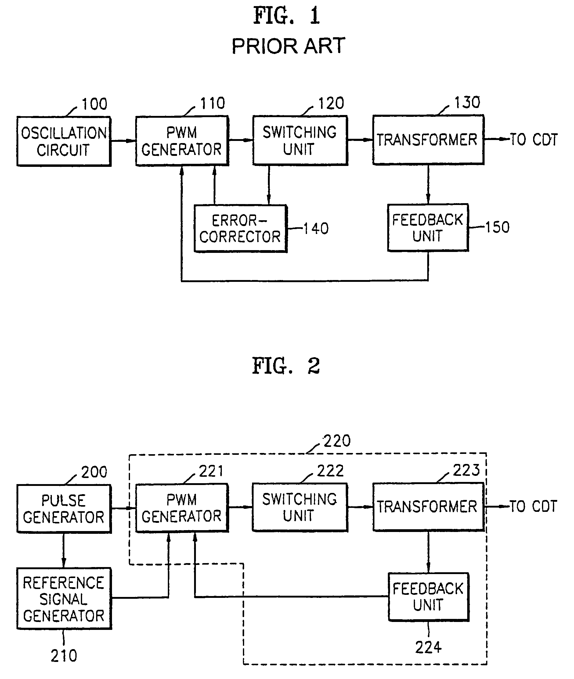
[0027]FIG. 2 is a block diagram of an apparatus generating a high-voltage regulation signal, according to an embodiment of the present invention.

[0028]The high-voltage regulation signal generation apparatus controlling regulation of a display comprises a pulse generator 200, a reference signal generator 210, and a high-voltage signal generator 220.

[0029]The pulse generator 200 generates a square wave pulse to synchronize a frequency of a regulation output voltage signal with a horizontal frequency of a display such as a CDT, to which a regulation voltage is supplied.

[0030]The reference signal generator 210 generates a reference signal with a desired duty ratio using a ...


PUM


Abstract

An apparatus to genearate a high-voltage regulation signal to control regulation of a display, including: a pulse generator to generate a pulse; a reference signal generator to generate a reference signal with a desired duty ratio using the pulse generated from the pulse generator; and a high-voltage signal generator to generate a switching signal with a duty ratio controlled by the reference signal, according to the pulse from the pulse generator and a feedback regulation output voltage, and to generate a high-voltage regulation signal according to the switching signal, wherein the feedback regulation output voltage is based upon the high-voltage regulation signal.

Description

CROSS-REFERENCE TO RELATED APPLICATIONS[0001]This application claims the priority of Korean Patent Application No. 2002-78717, filed on Dec. 11, 2002, in the Korean Intellectual Property Office, the disclosure of which is incorporated herein in its entirety by reference.BACKGROUND OF THE INVENTION[0002]1. Field of the Invention[0003]The present invention relates to a regulation circuit for a Color Display Tube (CDT), and, more particularly, to an apparatus and method for generating a high-voltage regulation signal capable of protecting components in a regulation circuit.[0004]2. Description of the Related Art[0005]Images on a bright area of a display screen sometimes appear as being expanded, and images on a dark area of the display screen sometimes appear as being contracted. This situation occurs because of a poor high-voltage regulation. Generally, image displays include a regulation circuit for controlling such a high-voltage regulation which has a direct influence on picture qu...

Claims


Application Information

Patent Timeline
IPC IPC(8): G09G5/00H04N3/185H04N5/44
CPCG09G5/00G09G2330/02H04N3/185
Inventor KO, SUNG-CHEOLKIM, HYUN-SUK
Owner SAMSUNG ELECTRONICS CO LTD
Why Eureka
Try Eureka