Optical system alignment system and method with high accuracy and simple operation

a technology of optical system and alignment system, applied in the direction of measuring devices, instruments, using optical means, etc., can solve the problems of diffraction-limited performance, mechanical indicators and their related tools do not have the required accuracy to align high-quality optical systems, and the first three techniques do not have the necessary alignment accuracy. achieve the effect of high accuracy and simple operation

Inactive Publication Date: 2007-05-29
ASML HLDG NV
View PDF2 Cites 7 Cited by
  • Summary
  • Abstract
  • Description
  • Claims
  • Application Information

AI Technical Summary

Benefits of technology

[0015]The present invention relates to an optical system alignment system and method with high accuracy and simple operation that substantially obviates one or more of the disadvantages of the related art.

Problems solved by technology

For optical systems requiring diffraction-limited performance (as needed for lithography optics), the first three of these techniques do not have the necessary alignment accuracy.
Aligning an optical system using mechanical indicators does not account for homogeneity errors that can have the same effect as a mechanical wedge.
Mechanical indicators and their related tooling (air bearing rotary tables, etc.) do not have the required accurately to align high quality optical systems, such as lithography optical systems.
Because a mechanical probe or an air gauge must either be in contact, or be in very close proximity, to the lens element being aligned, there are frequently mechanical interferences with the lens cell structure.
An alignment telescope's sensitivity is limited by the angular resolution of its optical system, the distance between the lens being aligned and the alignment telescope, and how well the alignment telescope optics are aligned.
Commercially available alignment telescopes do not have the required accuracy.
A custom-designed and fabricated alignment telescope has a limited range over which it can be used, because it works only for a limited range of lens radii of curvatures.
Alignment telescopes are difficult to use on short radii of curvature lens surfaces, due to the small amount of light captured by the alignment telescope aperture.
Alignment telescopes are also not usable with lenses and mirrors that have aspheric surfaces.
The asphericity causes the image reflected off the surface being aligned to be badly aberrated, making it impossible to achieve fine alignment tolerances.
Measuring an optical systems wavefront and distortion, and then back-calculating the alignment errors, is very time consuming and difficult, unless one starts with the optical system being relatively close to the optimum alignment condition.

Method used


Image

  • Optical system alignment system and method with high accuracy and simple operation
  • Optical system alignment system and method with high accuracy and simple operation
  • Optical system alignment system and method with high accuracy and simple operation

Examples


Embodiment Construction

[0025]Reference will now be made in detail to the preferred embodiments of the present invention, examples of which are illustrated in the accompanying drawings.

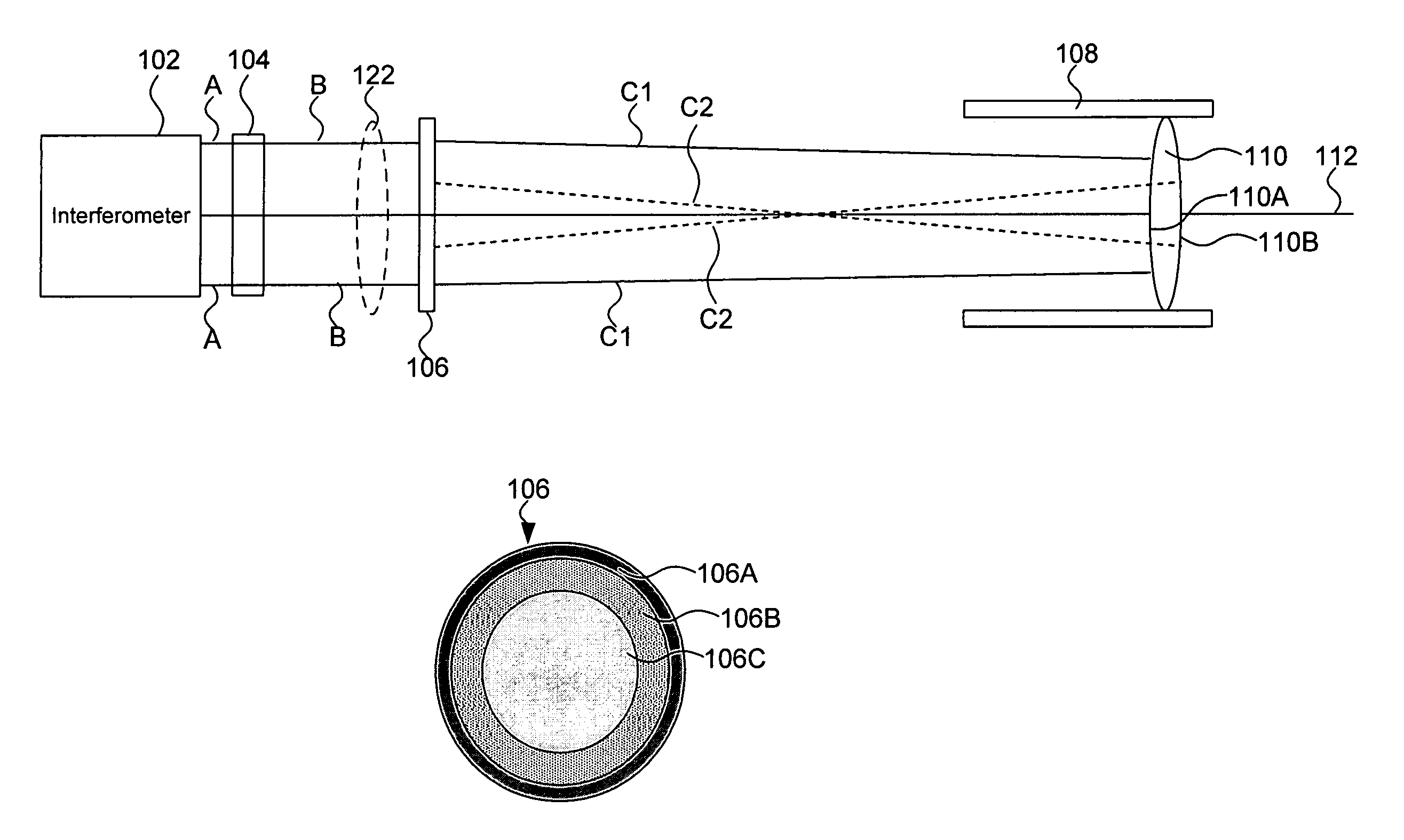
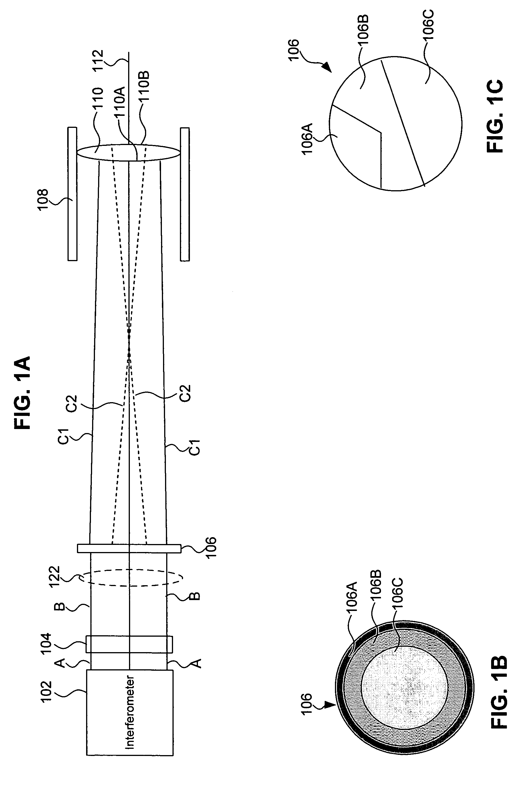
[0026]The proposed lens alignment technique uses an interferometer and diffractive optics, with specially designed alignment zones, to align optical systems containing lenses, mirrors and diffractive optics to sub-arc-second angular and sub-micron displacement tolerances. A diffractive alignment element is written preferably using lithographic technologies on a substrate. The grating pattern that is required is easily designed using commercially available optical design programs. The actual alignment process and data analysis is the same as used when testing spherical, aspherical optics using diffractive optics.

[0027]FIGS. 1A, 1B and 1C show an alignment system according to the present invention for use in lens alignment. FIG. 1A shows the overall system, and FIGS. 1B and 1C show exemplary diffractive elements that can be us...


PUM


Abstract

A system for aligning of optical components includes an interferometer and a first diffractive alignment element. A housing is used for positioning a first optical element being aligned. A detector is used for detecting fringes produced by reflections off surfaces of the first optical element. A grating pattern on the first diffractive alignment element is designed to produce a retro-reflected wavefront or a wavefront transmitted or reflected in a predetermined direction when the first optical element is in alignment. The first diffractive alignment element includes a first region for alignment of the interferometer, a second region for alignment of one surface of the first optical element, and a third region for alignment of another surface of the first optical element. The first, second and third regions can be of any shape such as circular, rectangular, triangular, or the like.

Description

CROSS-REFERENCE TO RELATED APPLICATIONS[0001]This application claims priority to U.S. Provisional Application No. 60 / 554,420, filed Mar. 19, 2004, titled “OPTICAL SYSTEM ALIGNMENT SYSTEM AND METHOD WITH HIGH ACCURACY AND SIMPLE OPERATION,” which is incorporated herein by reference in its entirety.BACKGROUND OF THE INVENTION[0002]1. Field of the Invention[0003]The present invention relates to alignment of optical components, and more particularly, to alignment of reflective and refractive optical components in high precision optical systems.[0004]2. Related Art[0005]Most multiple lens assemblies are currently aligned using one (or more) of the following methods:[0006](a) Mechanical indicators are used for either (or both) centering the outside diameter and minimizing the apparent wedge between lens surfaces relative to the lens cell;[0007](b) Alignment telescopes can be used for aligning centers of curvatures of the lens elements to a common optical axis;[0008](c) Fabricating the len...

Claims


Application Information

Patent Timeline
Patent Type & Authority Patents(United States)
IPC IPC(8): G01B9/02G01B11/27
CPCG01B11/272
Inventor HARNED, ROBERT D.HARNED, NORA-JEAN
Owner ASML HLDG NV
Why Eureka
Try Eureka