Reversible image display sheet and image display

a display panel and display panel technology, applied in the direction of static indicating devices, instruments, optics, etc., can solve the problems of slow response speed, lack of imaging repetition stability, and difficulty in maintaining a dispersion state stability

Inactive Publication Date: 2007-05-29
BRIDGESTONE CORP
View PDF6 Cites 12 Cited by
  • Summary
  • Abstract
  • Description
  • Claims
  • Application Information

AI Technical Summary

Benefits of technology

[0021](1) Enclosing two groups of particles with different charge characteristics between a pair of facing transparent substrates comprising a backlight, a color filter and two pairs of electrode, and across the substrates, an electric field being applied; then, displaying images by flying and moving the particles, an reversible image display panel with fast response speed and simple structure, being superior in stability and vividity is obtainable.
[0023](3) Enclosing a group of particles charged with single polarity between a pair of facing transparent substrates comprising a backlight, two kinds of electrodes, and a color filter, and across the substrates, an electric field being applied; then, displaying images by flying and moving the particles, an reversible image display panel with fast response speed and without electrostatic aggregation between the particles, being superior in repetition durability is obtainable.
[0024](4) Enclosing two groups of particles with different charge characteristics between a pair of facing substrates one of which is transparent, disposing a color plate on any one of the substrate, further providing at least two pairs of facing electrodes, applying voltage across the substrates in a manner that the electric potential on one electrode is higher than the electric potential on another electrode; then, displaying images by flying and moving the particles caused by the electric field induced by the applied voltage enables image display with fast response speed and simple structure, being superior in stability and vividity.

Problems solved by technology

However, in the electrophoresis method, there is a problem that a response speed is slow by the reason of viscosity resistance because the particles migrate among the electrophoresis solution.
Further, there is a problem of lacking imaging repetition stability, because particles with high specific gravity of titanium oxide is scattered within solution of low specific gravity, it is easy to subside, difficult to maintain a stability of dispersion state.
Even in the case of micro-encapsulation, cell size is diminished to a microcapsule level in order to make it hard to appear, however, an essential problem was not overcome at all.
However, with such a dry visual display device, there were the problems as the following:(1) The structure becomes complicated because a charge transport layer and a charge generation layer are disposed.(2) It is difficult to constantly dissipate charges from electroconductive particles, therefore two kinds of particles electrostatically aggregate while repeating display thereby not respond to electrostatic field, resulting in short longevity and lack of stability.(3) Colors become indistinct and lack luminance because the system utilizes the reflected-light from the particles for the display, resulting in the degradation of a vivid image display.(4) Because a generation of strong electric field is necessary in an occasion of driving, and because a design of the electric circuit that can bear the strong electric field, general purpose electronic materials are not employable.

Method used


Image

  • Reversible image display sheet and image display
  • Reversible image display sheet and image display
  • Reversible image display sheet and image display

Examples


example 1

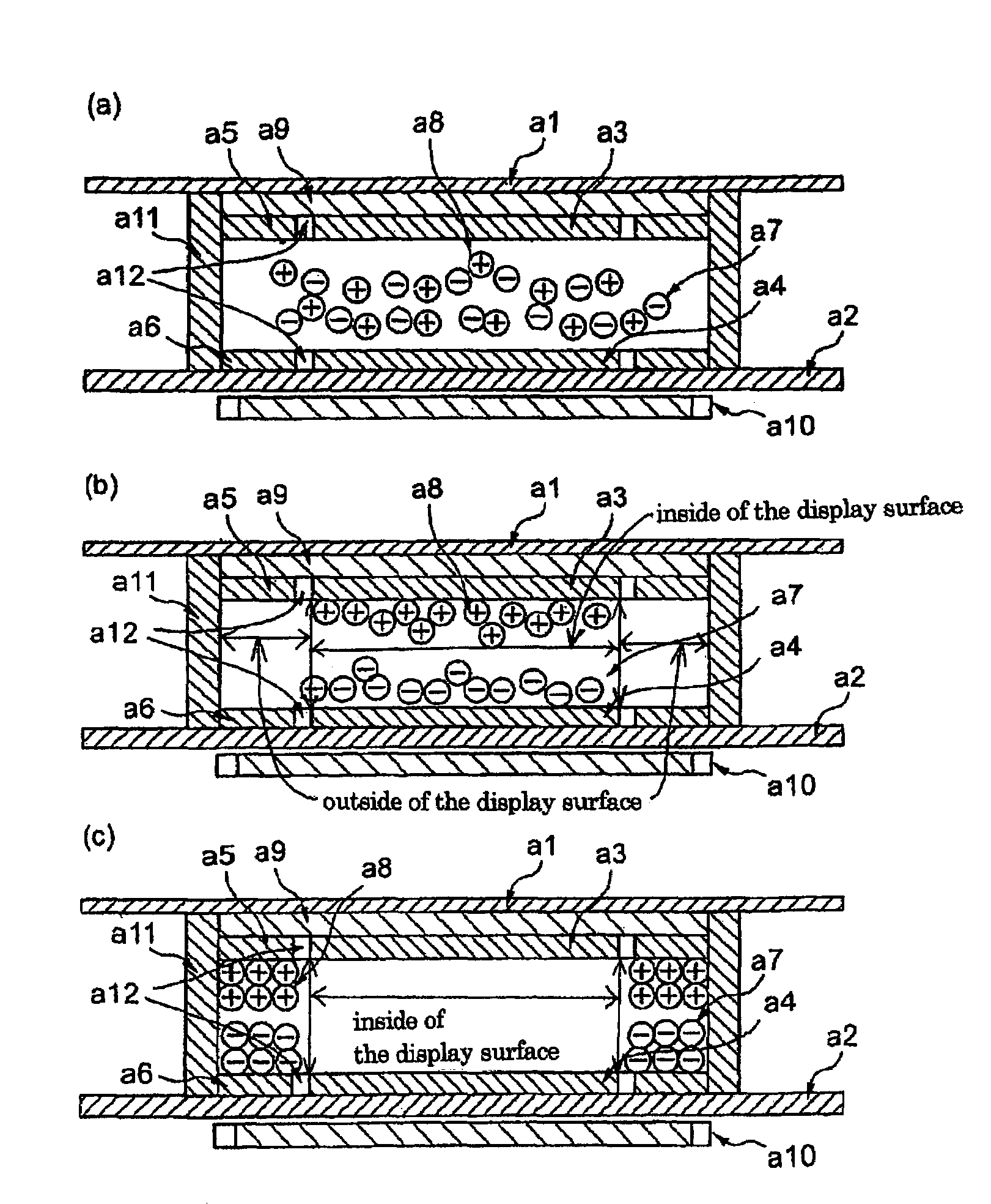
[0201]A reversible image display panel comprising a display element with a structure shown in FIGS. 1 was assembled. Glass substrates were employed as both the transparent substrate and the opposed substrate, ITO electrodes were employed as both the A electrode and the B electrode, and a copper electrodes were employed as both the C electrode and D electrode. Black polymerized toners (spherical toners with average particle diameter d0.5 of 8 μm, surface charge density of −40 μC / m2, the maximum surface potential of 450 V at 0.3 second after the foregoing surface potential measurement) for electrophotography were employed as the group of negatively chargeable particles. Black polymerized toners (spherical toners with average particle diameter d0.5 of 8 μm, surface charge density of +45 μC / m2, the maximum surface potential of 480 V at 0.3 second after the foregoing surface potential measurement) were employed as the group of positively chargeable particles. For the purpose of charging ...

example 2

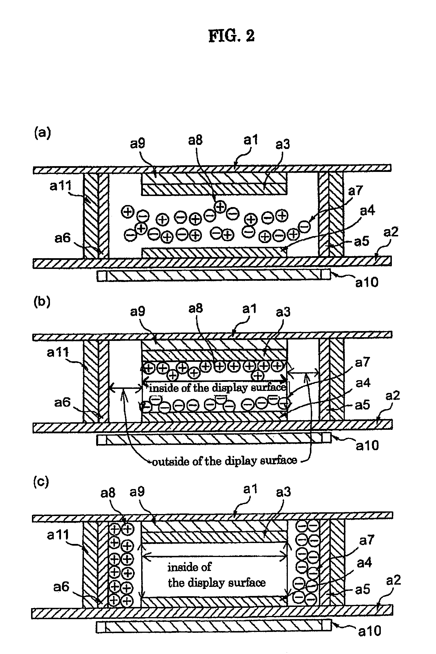
[0205]A reversible image display panel comprising a display element with a structure shown in FIGS. 4 was assembled. Glass substrates were employed as both the transparent substrate and the opposed substrate, ITO electrode was employed as the display electrode, and copper electrodes were employed as the counter electrodes. Over the surfaces of each electrodes, insulating silicone resin was coated with the thickness of about 3 μm for the purpose of preventing both adhesion and charge leakage. Black polymerized toners (spherical toners with average particle diameter d0.5 of 8 μm, surface charge density of −40 μC / m2, the maximum surface potential of 450 V at 0.3 second after the foregoing surface potential measurement) for electrophotography were employed as the group of negatively chargeable particles. Settling the height of the partition walls as 200 μm, the volume population of the particles among the space between the substrates was adjusted to 30%. Additionally, white resin sheet ...

example 3

[0209]A reversible image display panel comprising a display element with a structure shown in FIGS. 7 was assembled. Glass substrates were employed as both the transparent substrate and the opposed substrate, ITO electrode was employed as the display electrode, and copper electrodes were employed as the counter electrodes. Over the surfaces of each electrodes, insulating silicone resin was coated with the thickness of about 3 μm for the purpose of preventing both adhesion and charge leakage. Black polymerized toners (spherical toners with average particle diameter d0.5 of 8 μm, surface charge density of −40 μC / m2, the maximum surface potential of 450 V at 0.3 second after the foregoing surface potential measurement) for electrophotography were employed as the group of negatively chargeable particles. Settling the height of the partition walls as 200 μm, the volume population of the particles among the space between the substrates was adjusted to 40%. Additionally, red resin sheet wa...


PUM

PropertyMeasurementUnit
surface potentialaaaaaaaaaa
thicknessaaaaaaaaaa
thicknessaaaaaaaaaa

Abstract

A reversible image display panel which comprises a pair of substrates one of which is transparent and a group of particles charged with single polarity, a group of particles with single color charged with single polarity, a group of particles having portions with different colors and different charge characteristics, or two groups of particles with different charge characteristics each enclosed between the substrates, characterized in applying an electric field across the substrates, and displaying images by flying and moving the particles. The reversible image display panel and the image display device in accordance with the invention have fast response speed and simple structure, being superior in stability and vividity. In an occasion of driving, generation of the strong electric field is unnecessary for them and accordingly, electric circuits can be assembled employing general purpose electronic materials.

Description

TECHNICAL FIELD[0001]The present invention relates to a reversible image display panel and an image display device each enables to repeatedly display or eliminate images accompanied by flight and movement of particles utilizing Coulomb force, etc.BACKGROUND ART[0002]As an image display device substitutable for liquid crystal device (LCD), image display devices (displays) with the use of technology such as an electrophoresis method, an electrochromic method, a thermal method, dichroic-particles-rotary method are proposed.[0003]As for these image display device, it is conceivable as inexpensive visual display device of the next generation from a merit having wide field of vision close to normal printed matter, having smaller consumption power, and having a memory capability in comparison with LCD, spreading out to a display for portable device, and an electronic paper is expected.[0004]Recently, electrophoresis method is proposed that micro-encapsulate dispersion liquid made up with d...

Claims


Application Information

Patent Timeline
Patent Type & Authority Patents(United States)
IPC IPC(8): G02B26/00G02F1/1685
CPCG02F1/167G02F2001/1674G02F1/1671G02F1/1685
Inventor KITANO, HAJIMEYAKUSHIJI, GAKUMURATA, KAZUYANIHEI, NORIOTAKAGI, KOJIMASUDA, YOSHITOMOKAWAGOE, TAKAHIRO
Owner BRIDGESTONE CORP
Why Eureka
Try Eureka