Three-dimensional free space image projection employing Fresnel lenses

Inactive Publication Date: 2007-05-29
VIRRILLI JAMES
View PDF6 Cites 39 Cited by
  • Summary
  • Abstract
  • Description
  • Claims
  • Application Information

AI Technical Summary

Benefits of technology

[0028]Optionally, to provide flexibility in the layout and relative orientations of the projectors and optic module, one or more retro-reflectors, such as mirrors, can be arranged to reflect images projected by the projectors through the optic module.
[0029]Similar in operation to the first embodiment of the dynamic image projection system, the electronically controllable projectors utilized in the second embodiment of the dynamic image projection system project calculated images produced by a control device that performs image generation calculations and controls the projectors. This control device is capable of numerically calculating image information and using that information to control the characteristics of the projectors to project stereo images through the optic module in dynamic fashion. In embodiments of the invention wherein the projectors have liquid crystal imaging display elements incorporated therein, the imaging system is adapted to control the liquid crystal display elements within the projectors to modify the images being projected. The calculated image information relates to a desired three-dimensional image scene. The calculated image information in such embodiments causes the liquid crystal displays to be controlled in such a manner that a desired image is produced thereon, and light passes through the display and hits the optic module where its image light field is refracted and diffused in a known manner according to the characteristics of the Fresel lenses to produce free-space images that provide a perception of three-dimensional vision.
[0030]The control devices in both embodiments of the dynamic image projection system according to the present invention employ a feedback calculation to calculate the appropriate stereoscopic image pairs to be displayed at any given time. To calculate the derivative images for each LCD or projector in embodiments of the invention, the processor estimates the light directed to each one of a viewer's eyes by calculating interim calculated images for each of said LCDs/projectors, and then determines the combined light exiting each discrete pixel point of the optic module and the light formed at each pixel point of the output image p

Problems solved by technology

This approach, however, imposes increasingly large bandwidth requirements on image processing equipment.
As the images become more complex, this prior art embodying this approach has proven less and less successful.
This is a difficult task that has not been mastered in the p

Method used


Image

  • Three-dimensional free space image projection employing Fresnel lenses
  • Three-dimensional free space image projection employing Fresnel lenses
  • Three-dimensional free space image projection employing Fresnel lenses

Examples


first embodiment

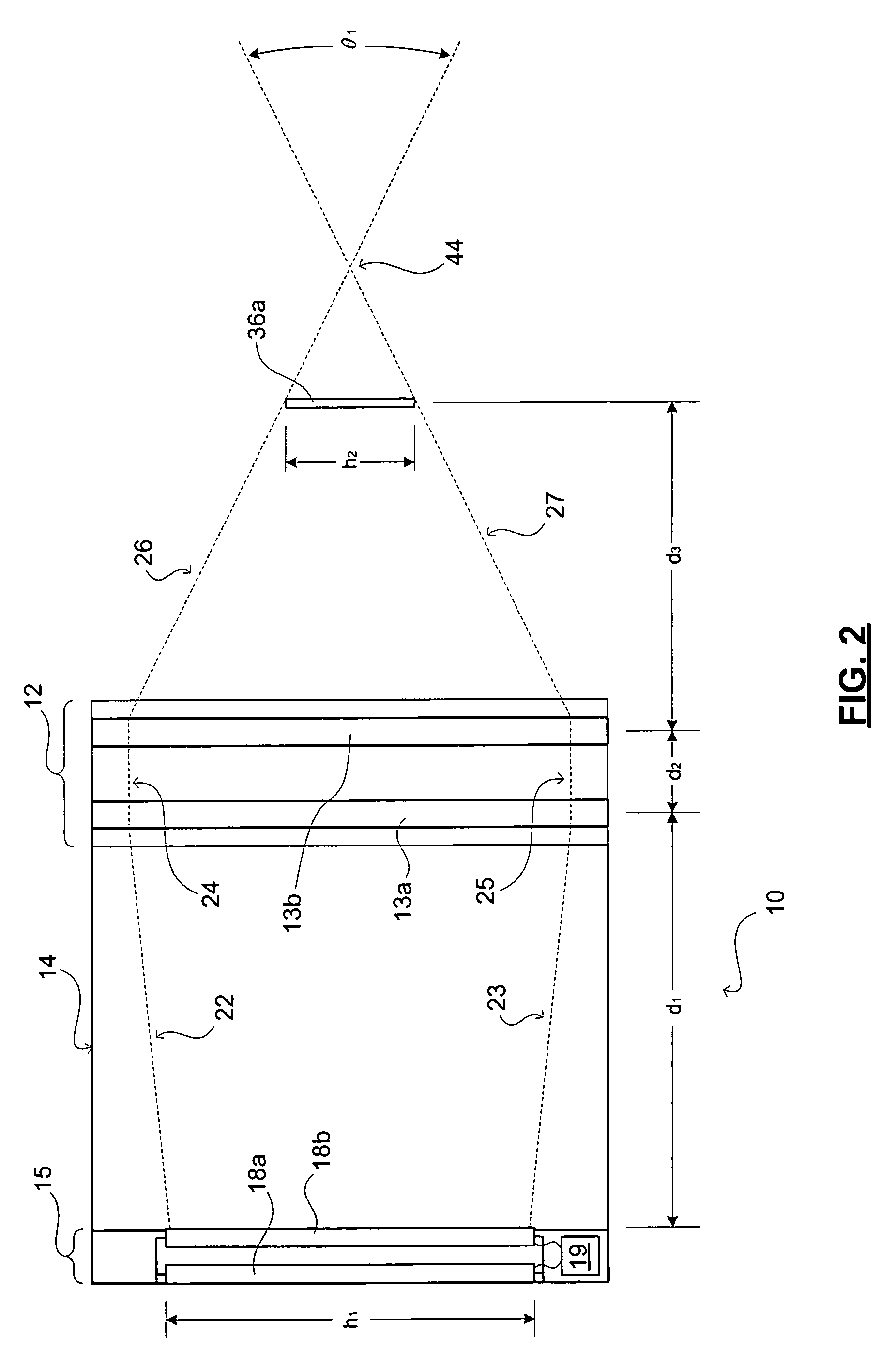
[0058]Referring now to FIG. 2, the imaging system 10 is represented from a side view. As depicted in FIG. 2, system 10 is configured having an optic module 12 that is formed of two large planar Fresnel lenses 13a and 13b mounted in parallel adjacently within a cabinet 14. For inclusion into an optic module 12, the Fresnel lenses 13a and 13b can typically be formed out of a transparent acrylic, and then sandwiched for sake of protection and support between two pieces of clear Plexiglas covering. The composite acrylic and Plexiglas lens can then be secured in a rectangular frame used to rigidly secure the lens within the optic module.

[0059]The exit optic or exit aperture of the optic module 12 is shown as the one side of the second planar Fresnel lens 13b. In this embodiment, the optic module 12 is supported by the cabinet 14 at a height above floor, such as would be a suitable level for accommodating standing observers. For example, cabinet 14 can be mounted within or formed as part ...

second embodiment

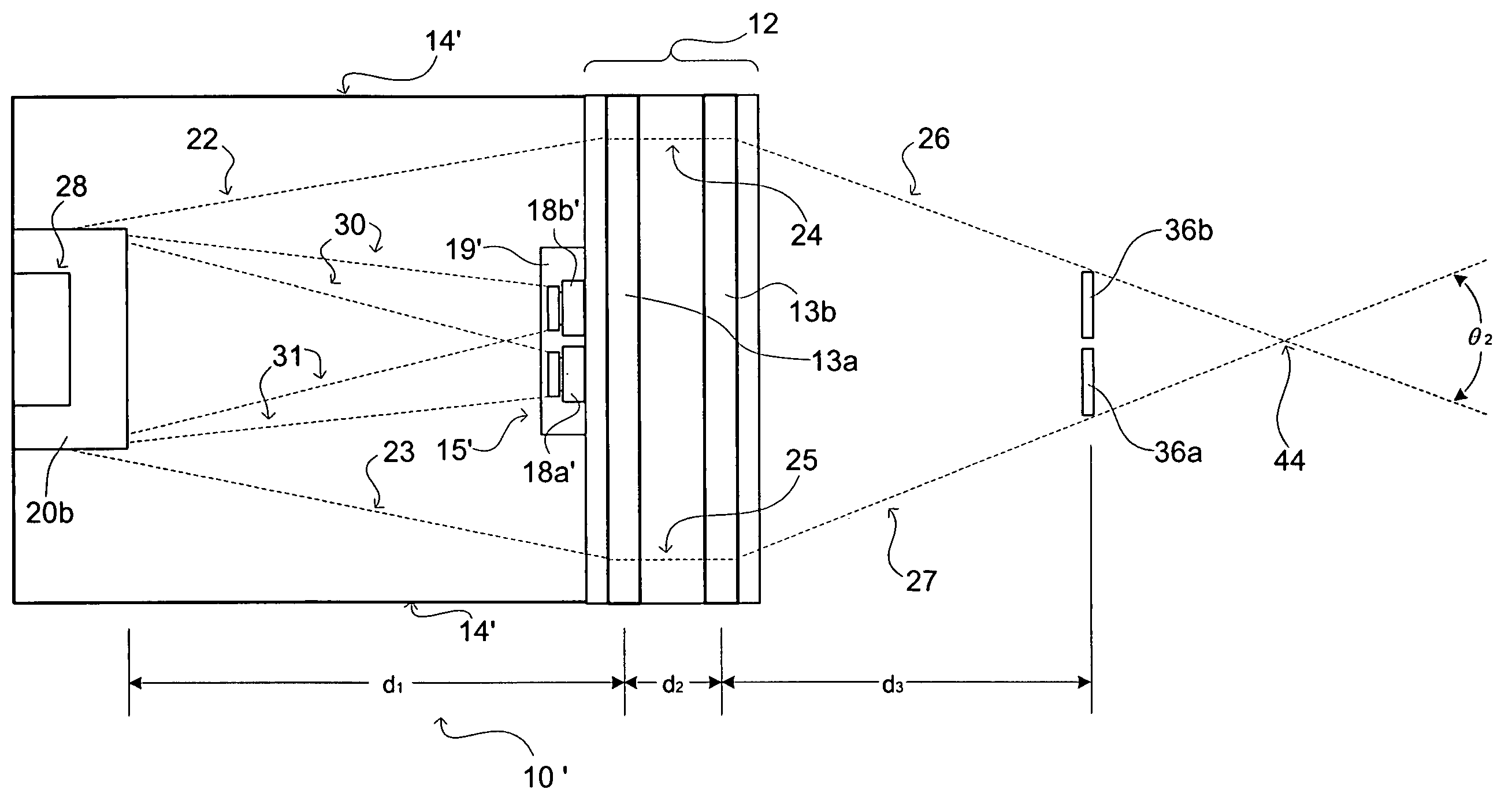
[0062]the imaging system 10′ will now be described with respect to FIG. 3 (in side view) and FIG. 4 (in top view). System 10′ is configured having an optic module 12 that is formed of two large planar Fresnel lenses 13a and 13b mounted in parallel adjacently within a cabinet 14′, similar in manner with respect to system 10 as described above. The optic module 12 for system 10′ can be formed of the same materials and have the same configuration as previously described.

[0063]The exit optic or exit aperture of the optic module 12 is shown as the right side of the second planar Fresnel lens 13b. In this embodiment, the optic module 12 is supported by the cabinet 14 at a height above the floor suitable level for accommodating standing observers.

[0064]In this second embodiment of the invention, the difference in the imaging system 10′ lies in the dynamic stereoscopic image projection system 15′. This projection system 15′ alternatively includes a pair of electronically controllable image ...


PUM


Abstract

Disclosed herein are three-dimensional free space imaging systems and related methods employing a dynamic stereoscopic image projection system in combination with a optic module comprising a doublet of Fresnel lenses. The dynamic projector systems calculating derived flat image information for each projector based upon inputted stereopair images and information regarding the projector elements and optic module. In preferred embodiments of the present invention, the projection system uses an image computational device that employs a neural network feedback calculation to calculate the appropriate flat image information and appropriate images to be projected on the screen by the projectors at any given time.

Description

REFERENCE TO RELATED APPLICATIONS [0001]This application is a continuation in part of U.S. non-provisional patent application Ser. No. 10 / 751,654, filed Jan. 6, 2004 and with the title “VISUALIZATION OF THREE DIMENSIONAL IMAGES AND MULTI ASPECT IMAGING” now U.S. Pat. No. 6.985,290, which application in turn is a continuation in part of U.S. non-provisional patent application Ser. No. 09 / 977,462, filed Oct. 15, 2001, now U.S. Pat. No. 6,717,728, which in turn is a Continuation-in-Part of U.S. patent application Ser. No. 09 / 456,826, filed Dec. 8, 1999 now abandoned.FIELD OF THE INVENTION [0002]The present invention relates to the projection of three-dimensional images into free space. More particularly, the present invention relates to apparatuses and related methods for three-dimensional image projection utilizing stereo aspect images projected through a Fresnel lens containing optic module.BACKGROUND OF THE INVENTION [0003]Projective displays use images focused onto or through a dif...

Claims


Application Information

Patent Timeline
IPC IPC(8): G02B27/22G03B21/26G09G5/00G02B13/06G02B27/00G03B35/24H04N13/00
CPCG02B27/0093G02B27/2214G02B27/225G03B35/24H04N13/0014H04N13/0055H04N13/0468H04N13/047H04N13/0475H04N13/0477H04N13/0495H04N13/0497H04N13/0404H04N13/0409H04N13/0434H04N13/0438H04N13/117H04N13/189H04N13/305H04N13/31H04N13/337H04N13/341H04N13/366H04N13/368H04N13/373H04N13/376H04N13/395H04N13/398G02B30/27
Inventor PUTILIN, ANDREY N.LUKYANITSA, ANDREW
Owner VIRRILLI JAMES
Why Eureka
Try Eureka