Dynamic objects with property slot definition and runtime mechanisms

a technology of dynamic objects and runtime mechanisms, applied in the direction of user interface execution, web data retrieval, instruments, etc., can solve the problems of inability to expect that domain experts have the time or inclination inability to graphically visualize the entire system of existing component technologies, and inability to achieve the time or inclination of domain experts to become professional programmers

Active Publication Date: 2007-05-29
TRIDIUM
View PDF37 Cites 29 Cited by
  • Summary
  • Abstract
  • Description
  • Claims
  • Application Information

AI Technical Summary

Benefits of technology

[0005]One aspect of the present invention is a software program whose code includes one or more components of the same component-type for execution on a machine. The components of that software program are generated by a specified method. In that method a base class is provided to a framework, the base class comprising one or more slot definitions at least one of which is a property slot definition. All the property slot definitions in the base class are identified. For each of these property slot definitions getter and setter methods are located. A component type object, which is configured to store slot definitions is generated. The identified property slot definitions are then stored in that component type object. One or more components are generated. Each of these components has a slotmap object, which is instantiated from the slot map class. Each slot map object also includes values for each property slot definition stored in the component-type object. Each value is associated with a single component thereby providing the ability to store data that is unique to each component.

Problems solved by technology

This process is error prone, time consuming and fraught with miscommunication.
It is not feasible to expect that domain experts have the time or inclination to become professional programmers.
However, known prior approaches still require knowledge of a programming language in order to implement a practical system.
Furthermore, existing component technologies do not allow the domain expert to graphically visualize the entire system and make changes at runtime.
This exploratory programming approach is at odds with current solutions which require the software to be stopped, recompiled, and then restarted.
Stopping of the software may be especially difficult in some environments where critical processes are being controlled.
Another specific challenge in providing such a solution is the need to allow the domain expert to enhance or extend software components to adapt them to the unique needs of a specific domain application.

Method used


Image

  • Dynamic objects with property slot definition and runtime mechanisms
  • Dynamic objects with property slot definition and runtime mechanisms
  • Dynamic objects with property slot definition and runtime mechanisms

Examples


Embodiment Construction

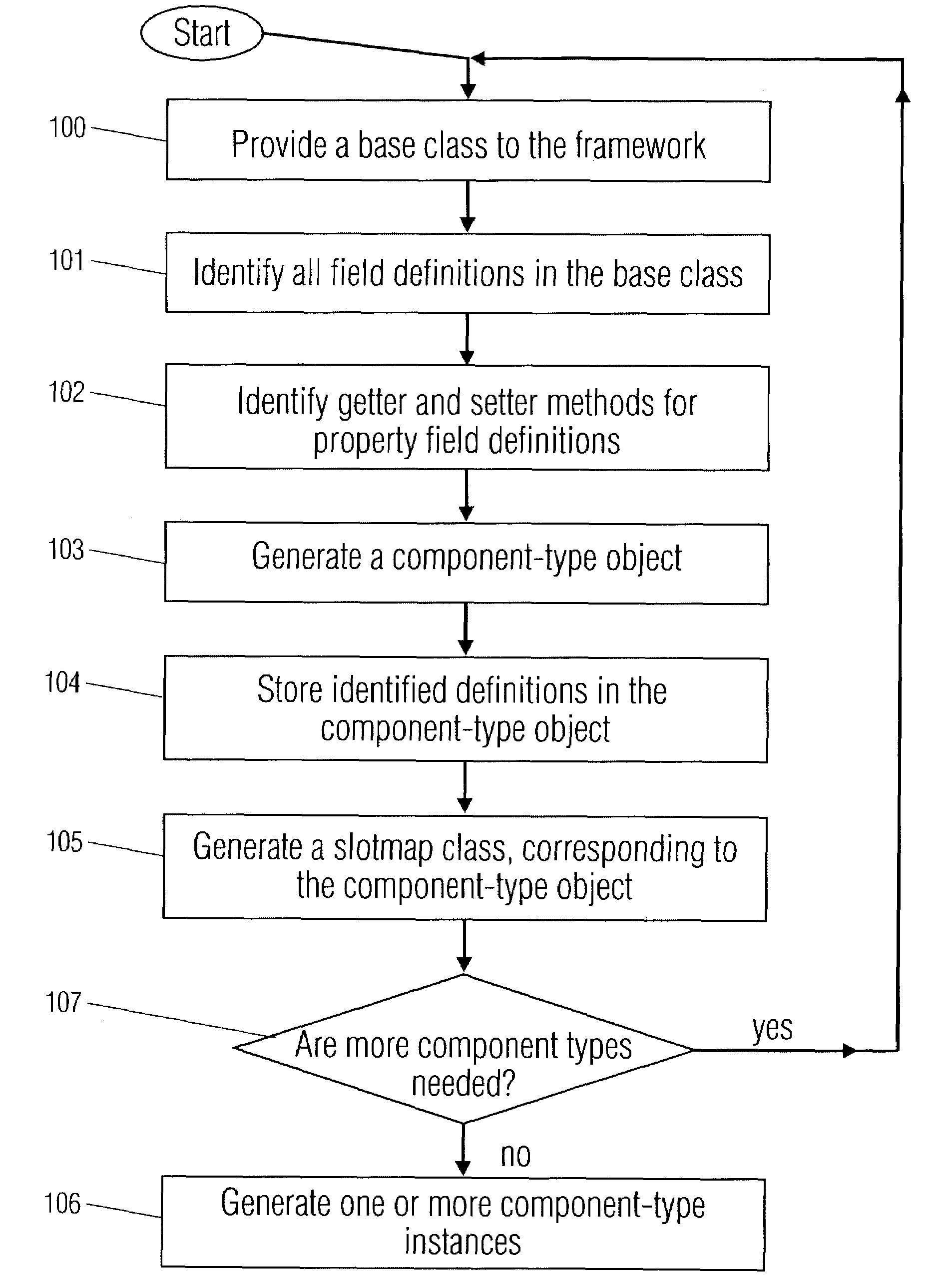
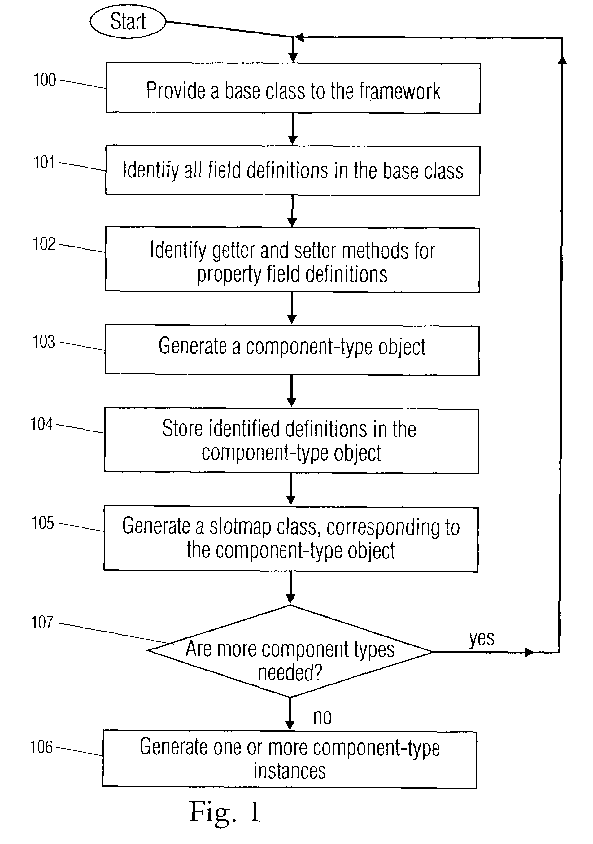
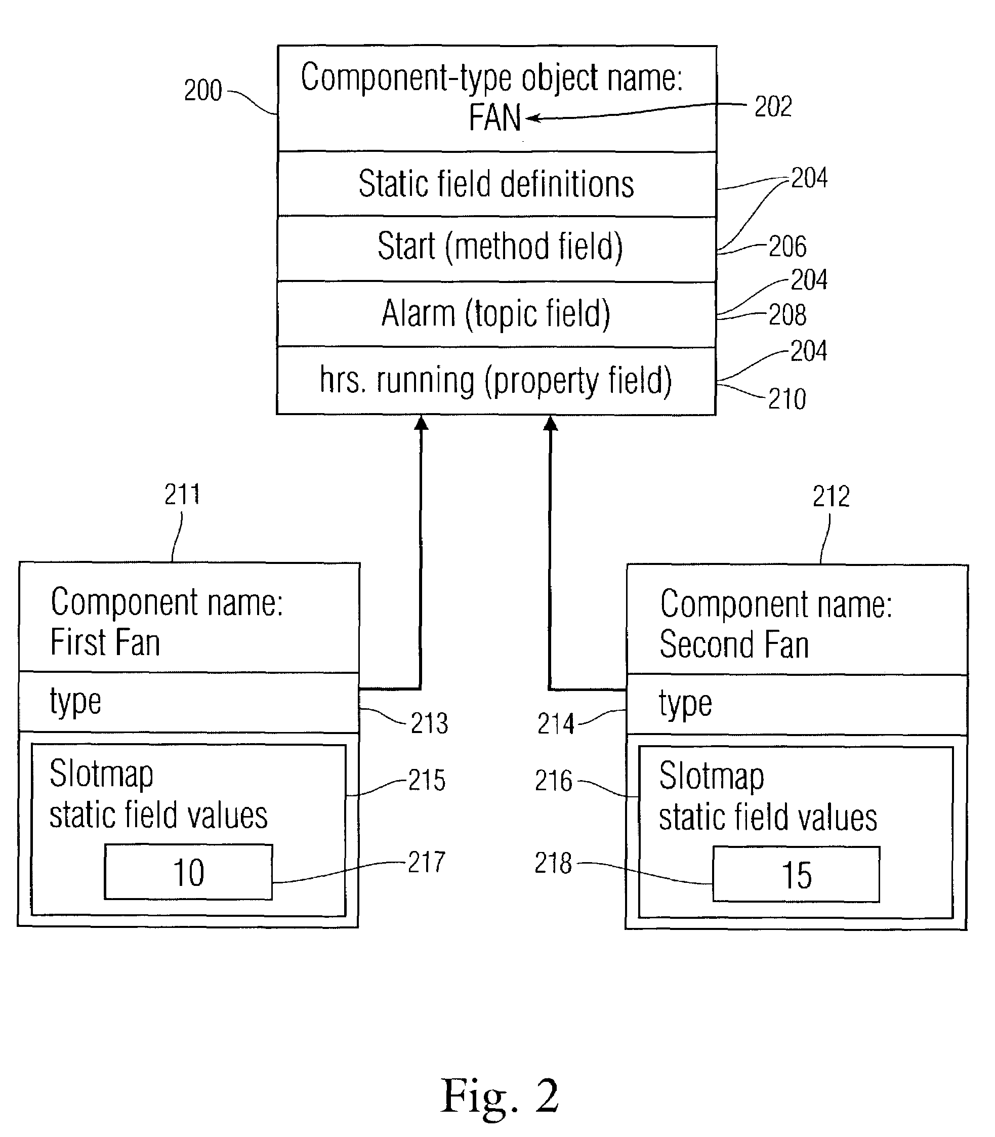
[0019]The component model of the present invention provides a unique component design for software components that allows application developers to extend and modify software components in a graphical environment suitable for non-programmers. The component model design enables new slots, such as properties, actions or topics to be added to standard components without the software coding steps that would typically be required.

[0020]A component model approach to software development allows software components to be created that have a direct relation to the end use application, while still capitalizing on the benefits of object oriented software design. As such, components provide a higher level of abstraction than is present in a pure object-oriented approach. Where objects encapsulate behaviors that are applicable to software functions (such as handling a string, providing buffer management, etc), components may assemble objects to meet the needs of end application goals (such as pr...


PUM


Abstract

A component based software program, where each component is based on a component-type. Component-types are created from base classes comprising slot definitions. The slot definitions are identified and stored in a component-type object. One or more components of the component-type are created, each comprising a reference, to a component-type object and a slotmap having storage locations for values associated with property slots definitions, in the component-type object. Values for property slots are entered into components by being placed in the storage locations. Also disclosed is a method for automatically designating unique names to components. One root component is created. Further non-root components are placed within the root component or within other components, so that all components form a tree structure. A component is assigned a unique identification string, comprising a sequential list of all of the component's ancestors and the component's name.

Description

[0001]This patent application claims the benefit of priority under 35 U.S.C. 119(e) from U.S. Provisional Patent Application Ser. No. 60 / 357,329, filed Feb. 15, 2002, entitled “COMPONENT MODEL FOR REAL-TIME SYSTEM CONTROL”, which is hereby incorporated by reference as if set forth in its entirety herein.BACKGROUND OF THE INVENTION[0002]Many different endeavors require custom software to solve their problems. Typically these problems are well understood by domain experts, such as, for example building automation experts, factory automation experts, and traffic control experts. However it is rare that domain experts have the required skills to use common programming techniques such as object oriented programming. Today domain experts must attempt to specify their requirements to programmers who then build the desired system. This process is error prone, time consuming and fraught with miscommunication. What is needed is the ability for domain experts who understand the problem space t...

Claims


Application Information

Patent Timeline
Patent Type & Authority Patents(United States)
IPC IPC(8): G06F9/44G06F15/16G06F17/30
CPCG06F8/34G06F8/36G06F9/4443G06F17/3089G06F17/30905G06F9/451G06F16/9577G06F16/958
Inventor FRANK, BRIAN SPENCERSUBLETT, JOHN W.
Owner TRIDIUM
Why Eureka
Try Eureka