Siding clip

a technology for siding and clips, applied in the direction of snap fasteners, buckles, haberdashery, etc., can solve the problems of siding installers, siding sections will expand or contract in accordance with the thermal expansion of materials, care must be taken, etc., to achieve quick and easy installation or removal, simple design, and easy and efficient use of siding clips

Inactive Publication Date: 2007-06-05
DAVIS SCOTT A
View PDF7 Cites 27 Cited by
  • Summary
  • Abstract
  • Description
  • Claims
  • Application Information

AI Technical Summary

Benefits of technology

[0016]The present invention provides a substantial improvement over the prior art. For example, as the lower fold section of the siding clip secures the siding within the C-shaped bend section, the siding clip may be quickly and easily installed or removed from a siding section by merely sliding the siding clip downwards from the top of the siding section, the siding clip then “popping” into place with the siding section secured within the C-shaped bend section. Also, because the top edge of the siding section fits within the siding edge receiving and retaining structure and the spring bias the clip upwards relative to the siding section, the siding is additionally secured within and by the siding clip. Furthermore, because the siding section is also supported by the generally C-shaped bent section of the clip, thermal expansion and contraction of the siding section will not affect the securement characteristics of the siding clip and the siding is therefore free to slidably move within the clip. Finally, the relatively simple design of the present invention permits easy and efficient use of the siding clip as compared with other devices found in the prior art. It is therefore seen that the present invention provides a substantial improvement over those devices found in the prior art.

Problems solved by technology

Each type of siding has various advantages and disadvantages, however, metal and vinyl siding types have become more popular due to their longevity and minimal care needs.
While each of these clips perform their intended function with some degree of efficiency, there are deficiencies with the use of each of the various clips which are not addressed.
For example, a common complaint from siding installers is that most, if not all, of the clips presently available in the prior art require the clip to be installed on the siding prior to the installation of the siding, as is shown in the Wood Patent.
Another problem that is common with both metal and vinyl siding is that as the outside temperature changes, the siding section will expand or contract in accordance with the materials thermal expansion coefficient.
Of course, one of the difficulties with such nail slots is that in driving the nail into the building wall, care must be taken to not drive the nail too deeply into the wall to prevent movement of the siding due to frictional interference by the nail, which is a commonly occurring problem when nail guns or the like are used to apply the siding.
Finally, a problem with the prior art clips is many of the more useful and popular clips rely on the semi-rigid construction material to provide the frictional contact which secures the clip on the siding section.
However, as the clip ages, the strain on the material does not lessen and the metal or plastic construction material fatigues which can accidentally release the siding section from the clip.

Method used


Image

  • Siding clip
  • Siding clip
  • Siding clip

Examples


Embodiment Construction

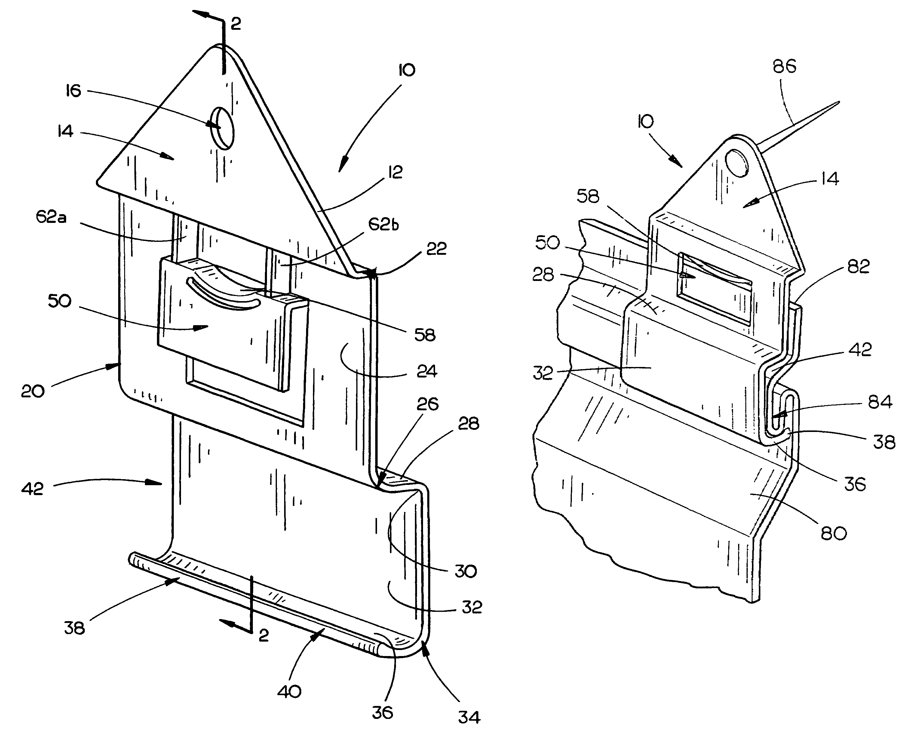
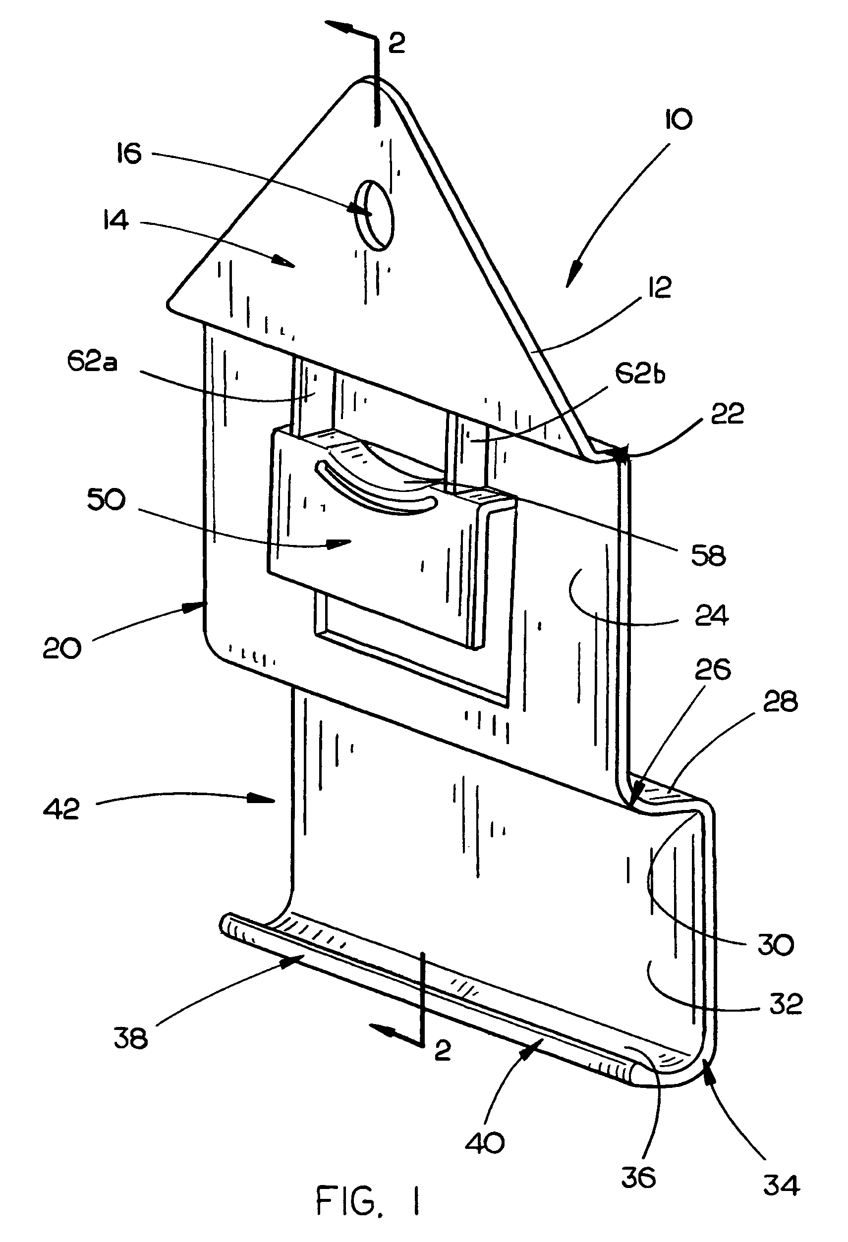
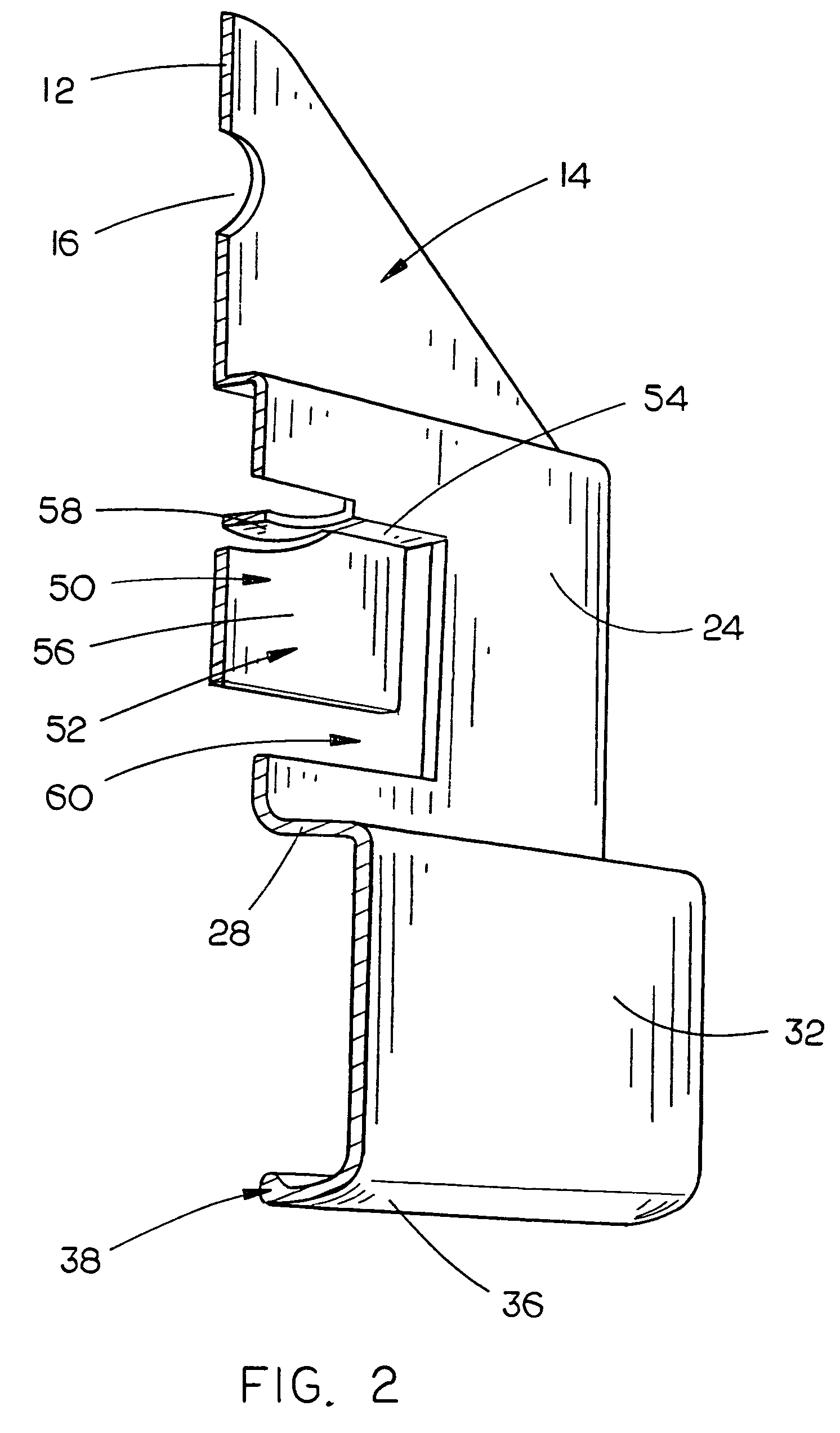
[0020]The siding clip 10 of the present invention is shown best in FIGS. 1 and 2 as being initially constructed of a single metal or plastic sheet having a width of approximately two to four inches, a height of approximately three to six inches, and a wall thickness of approximately 0.02 to 0.05 inches. The generally planar sheet 12 includes two major sections, the first being an upper generally triangular securement section 14 and the second being a lower fold section 20 which is operative to mount the siding clip 10 on the siding section 80 to which the siding clip 10 is to be mounted. It should be noted, however, that the description of the planar sheet 12 as including the upper securement section 14 and lower fold section 20 is done for convenience of the description of the preferred embodiment and should not be understood to represent specific structural elements or restrictions for the siding clip 10 of the present invention. Also, it is expected that construction of the sidin...


PUM


Abstract

An improved siding clip includes a planar sheet having a lower fold section having a lower end and an upper generally triangular securement section including at least one fastener hole formed therein. The lower fold section includes a generally upright upper section generally adjacent the upper triangular securement section, and a siding edge receiving and retaining structure is mounted on the upper section of the lower fold section which includes a generally L-shaped wall extending rearwards and downwards from the upper section and a plate spring mounted adjacent the generally L-shaped wall operative to bias the siding clip upwards relative to the siding section held within the generally L-shaped wall to frictionally secure the siding clip on the siding section. The lower fold section is bent forwardly, then downwardly and then rearwardly to form a general “C”-shape channel operative to receive and retain a siding portion therein.

Description

BACKGROUND OF THE INVENTION[0001]1. Technical Field[0002]The present invention relates generally to the attachment of vinyl siding to a building, and more particularly to an improved siding clip for mounting siding which includes a planar sheet having a lower fold section having a lower end and an upper generally triangular securement section including at least one fastener hole formed therein. The lower fold section includes a generally upright upper section generally adjacent the upper triangular securement section, and a siding edge receiving and retaining structure is mounted on the upper section of the lower fold section which includes a generally L-shaped wall extending rearwards and downwards from the upper section and a plate spring mounted adjacent the generally L-shaped wall operative to bias the siding clip upwards relative to the siding section held within the generally L-shaped wall to frictionally secure the siding clip on the siding section. The lower fold section is ...

Claims


Application Information

Patent Timeline
Patent Type & Authority Patents(United States)
IPC IPC(8): E04D1/34E04D1/00E04F13/08
CPCE04F13/0864Y10T24/304
Inventor DAVIS, SCOTT A.
Owner DAVIS SCOTT A
Why Eureka
Try Eureka