

CVT frame member
- Summary
- Abstract
- Description
- Claims
- Application Information
AI Technical Summary
Benefits of technology
Problems solved by technology
Method used
Image

Examples
Embodiment Construction
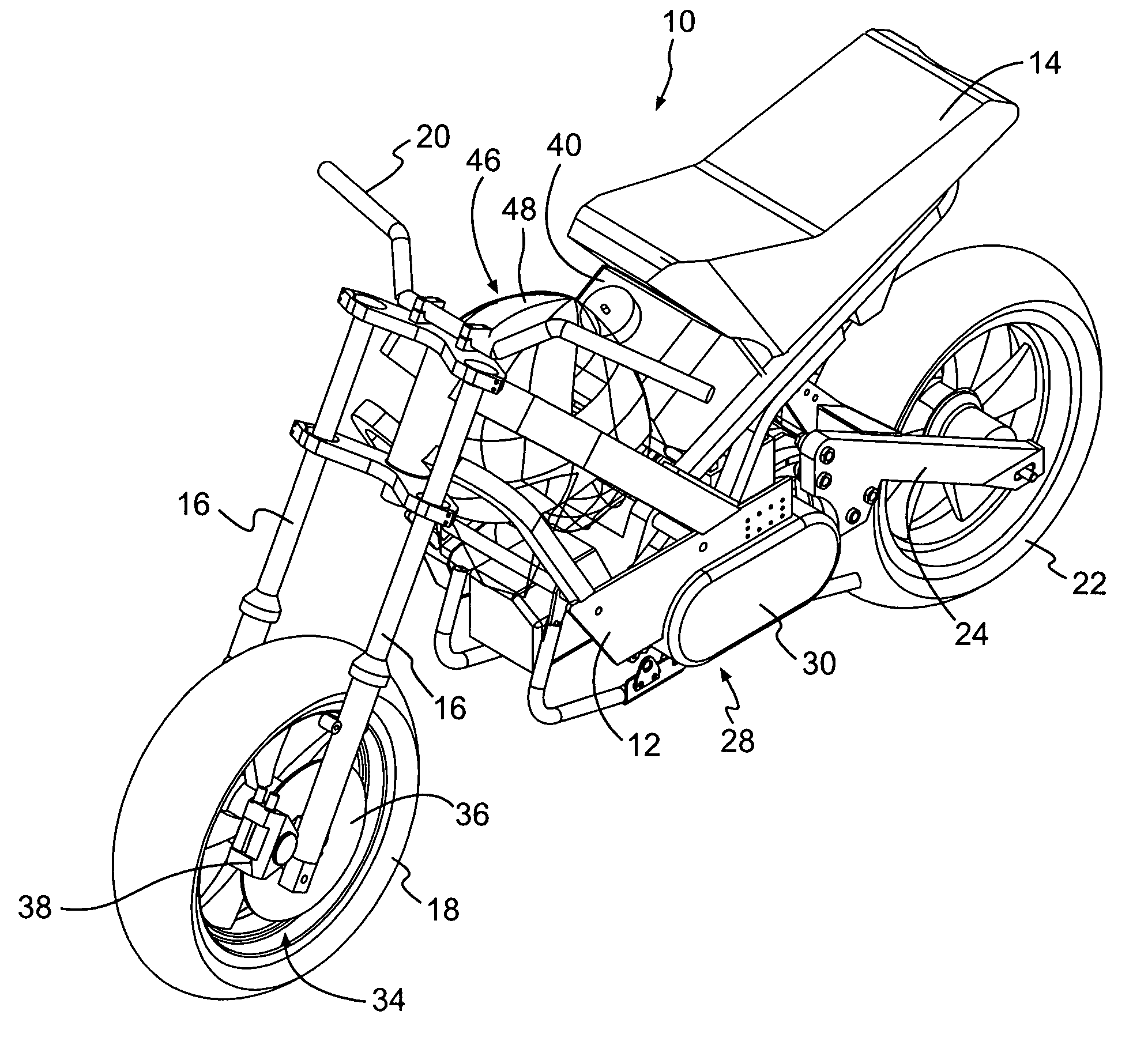
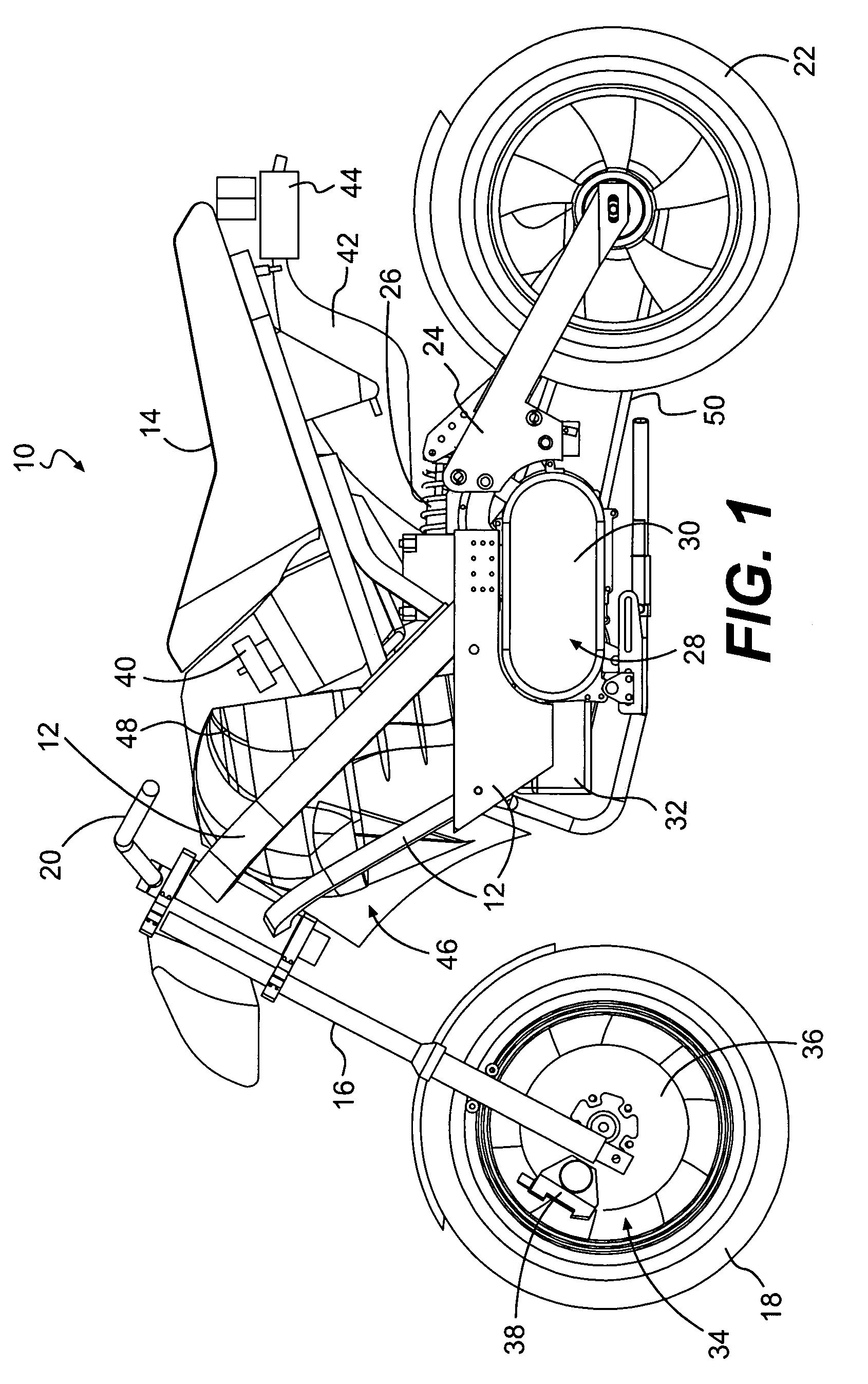
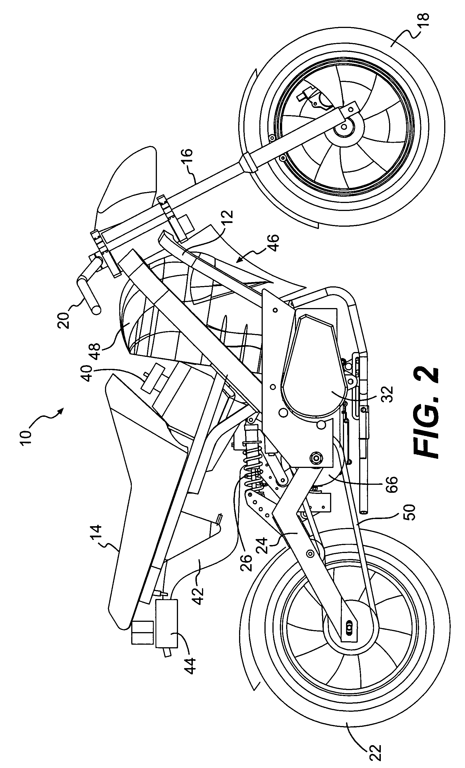
[0030]FIG. 1 illustrates a two-wheeled vehicle 10 constructed in accordance with one embodiment of the present invention. The two-wheeled vehicle 10 includes a frame 12. A straddle-type seat 14 is disposed on the frame 12 and is constructed and arranged to accommodate at least one rider thereon, the driver of the vehicle 10. If a second rider accompanies the driver 10, the second rider, also referred to as a first passenger, will straddle the straddle-type seat in a position behind the driver.
[0031]The vehicle 10 includes a front suspension 16, which is a forked suspension typical for two-wheeled vehicles. A front wheel 18 is disposed on the front suspension 16. Handlebars 20 are connected to the front suspension 16 to provide steering control of the front wheel 18. While a forked front suspension is preferred for the invention, other constructions for the front suspension 16 may be employed without departing from the scope of the invention. For example, an asymmetrical front suspen...
PUM
 Abstract
Description
Claims
Application Information