Device for mounting an object at the corner of a room

a technology for mounting devices and objects, applied in the direction of light support devices, washstands, scaffold accessories, etc., can solve the problems of difficulty in assembling and positioning during use, other mounting devices may lack complexity, but usually lack versatility, etc., and achieve the effect of quick and easy manner

Inactive Publication Date: 2007-06-05
FEELEY T J
View PDF9 Cites 25 Cited by
  • Summary
  • Abstract
  • Description
  • Claims
  • Application Information

AI Technical Summary

Benefits of technology

[0014]The second mounting member includes a body member and a overhang portion which together define a flange receiving area for receipt of top retaining flange of first mounting member when attaching the desired object at the corner. The second mounting member can also be provided with an alignment or securement aperture, with or without threads. When the second mounting member is properly secured to the first mounting member, the respective apertures are substantially aligned to permit a screw, bolt, rivet, etc. to be inserted and further secure the second mounting member to the first mounting member 50. The bottom ledge of the first mounting member can also provide support for the second mounting member and its associated object.
[0015]In either embodiment, the mounting assembly permits the desired object to be securely mounted in a room at a corner area, in a safe and attractive configuration.
[0018]It is another object of the present invention to provide a mounting assembly which permits mounting of an object at a corner area of a room in a relatively quick and easy manner.

Problems solved by technology

Many mounting devices include a plethora of parts and components, and are difficult to assemble and position during use.
Other mounting devices may lack complexity but usually lack any versatility.

Method used


Image

  • Device for mounting an object at the corner of a room
  • Device for mounting an object at the corner of a room
  • Device for mounting an object at the corner of a room

Examples


first embodiment

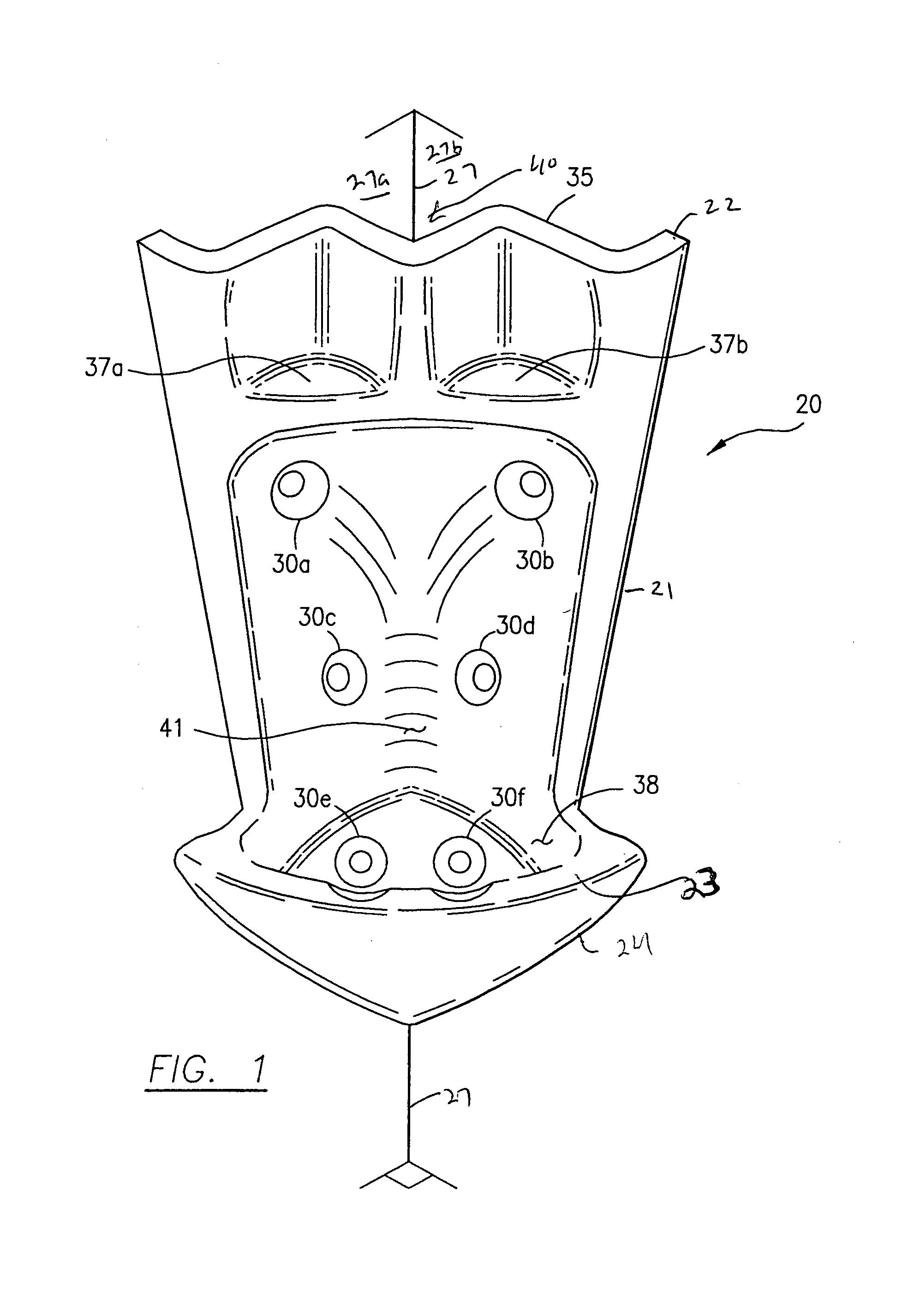
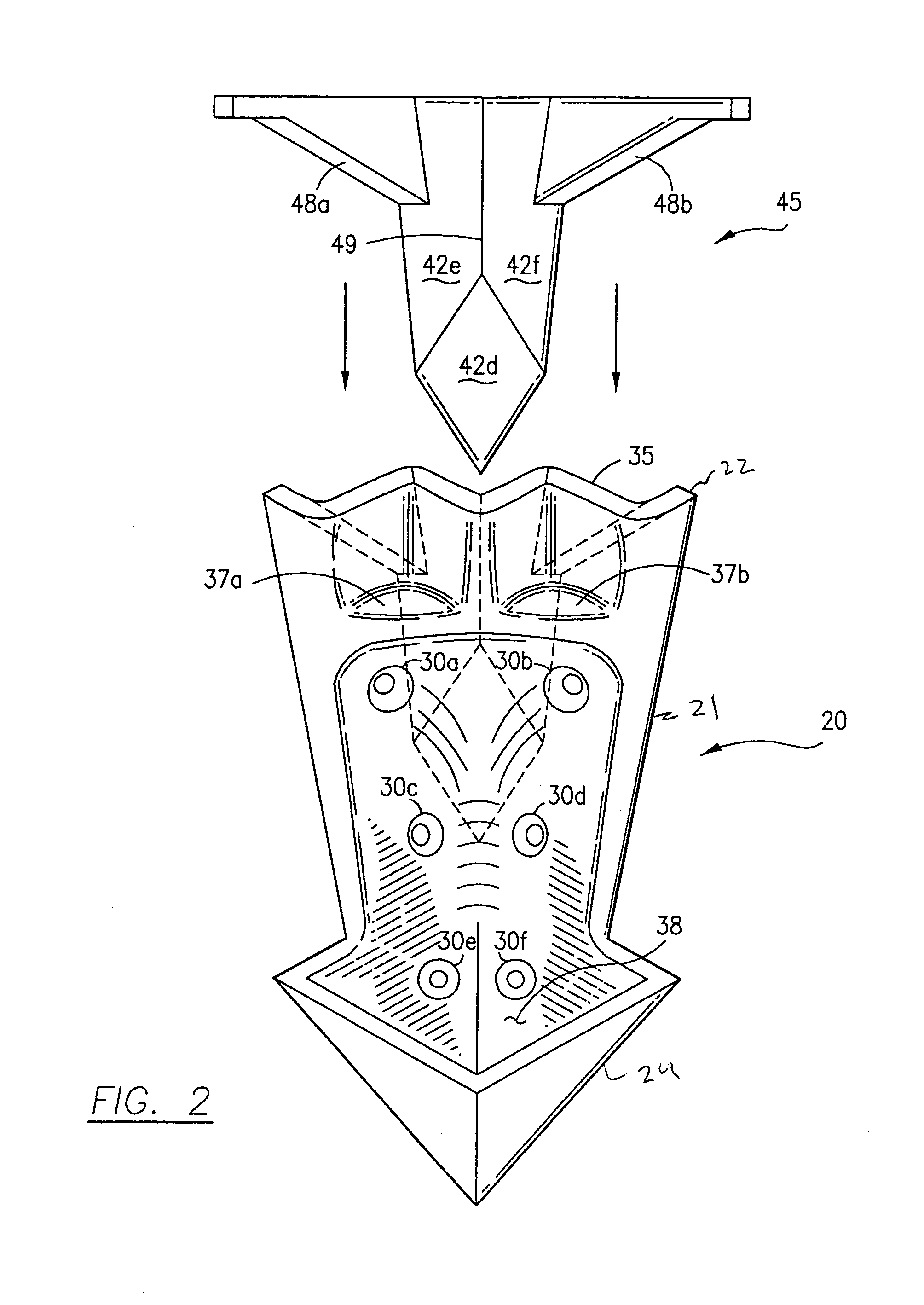
[0036]Referring to FIGS. 1–3, the present invention device for mounting an object at an interior corner of a room is illustrated and generally designated as mounting device 20. Mounting device 20 includes a body member 21 having a top end 22 and a bottom end 24. The shape, material and / or exterior appearance of body member 21 can correspond to the shape, material and / or exterior appearance of the object to be mounted by mounting device 20;

[0037]Top end 22 includes at least one substantially V-shaped edge, and preferably a fan or accordion shaped edge 35 having a central substantially V-shape edge portion. V-shaped edge portion 35 in conjunction with a tapered or cutout top back portion 39 of body member 21 define a female receiving portion 40 of mounting device 20 (in conjunction with the room walls) for receiving a male mounting or insertion portion 45 provided with an object 29 intended to be mounted at a corner 27 of room. The shape of the back female receiving portion 40 can be ...

second embodiment

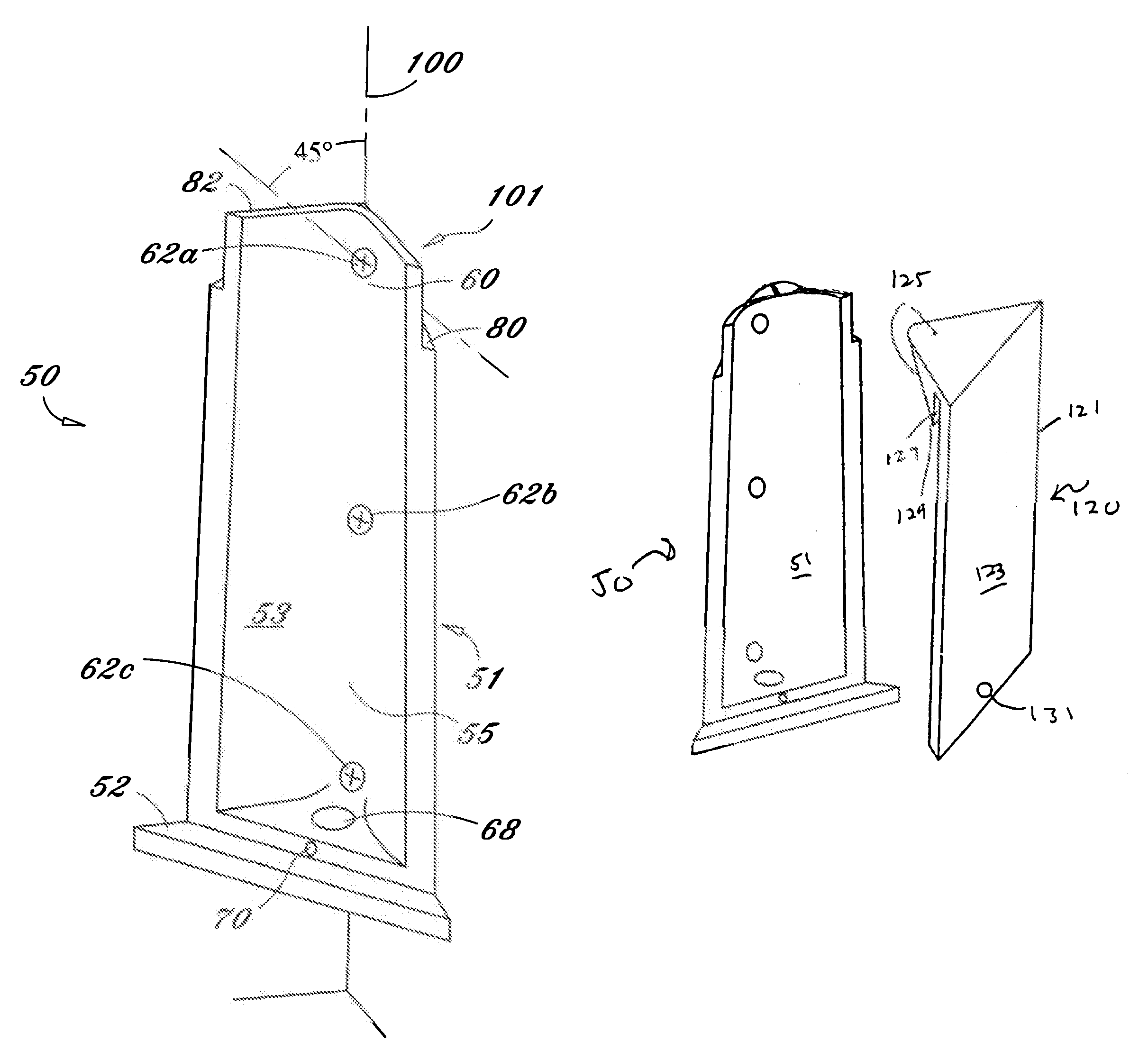
[0044]As seen in FIG. 8 a second embodiment for the mounting assembly of the present invention is illustrated and can include a first mounting member generally designated as reference numeral 50 and a second mounting member generally designated as reference numeral 120.

[0045]As seen in FIG. 4, first mounting member 50 includes a body member 51. A ledge or platform 52 can be provided at the bottom of body member 51. A top-retaining flange 82 can be provided at the top of body member 51 and along with body member 51 defines a lip area 80. Body member 51 can be provided with one or more apertures 62, which in conjunction with corresponding mounting screw(s) or similar fasteners, retain or secure body member 51 to the wall of a room. The location of mounting apertures 62 on body member 51 can be selected such that mounting apertures 62 and their corresponding or associated mounting screws are not seen when the object is properly mounted at corner 100.

[0046]As seen in FIG. 4, body member...


PUM


Abstract

An assembly for mounting an object at a corner area of a room. A first embodiment includes a mounting member having a rear cutout. The mounting member is secured to the walls adjacent the corner to define a receiving area for receipt of an insertion member attached to the object. A lower portion of the object can also rest upon a ledge portion of the mounting member. In a second embodiment, a first mounting member having a top flange is secured at the corner. A second mounting member attached to the object defines an area for receiving the top flange. The mounting members can be provided with lower apertures that are aligned with each other for insertion of a retaining screw. The second mounting member can also be supported at a bottom ledge of the first mounting member.

Description

BACKGROUND OF THE INVENTION[0001]1. Field of the Invention[0002]The present invention relates to a device for mounting an object at an interior corner of two intersecting walls.[0003]2. Description of Related Art[0004]Mounting devices are available in many configurations and enable the placement of various objects for wall display and / or storage. Many mounting devices include a plethora of parts and components, and are difficult to assemble and position during use. Other mounting devices may lack complexity but usually lack any versatility.[0005]Exemplary mounting devices include U.S. Pat. No. 939,005 to Goedeke (Goedeke). Goedeke relates to a corner iron for bread and laundry baskets. The corner iron of Goedeke is stamped from a single piece of sheet metal and folded to form angular related sides and a reinforced bottom.[0006]U.S. Pat. No. 4,727,815 to Miller relates to a corner shelf assembly, which is adapted to be mounted in a wall corner having two wall surfaces intersecting wi...

Claims


Application Information

Patent Timeline
Patent Type & Authority Patents(United States)
IPC IPC(8): A47B96/06A47G29/00A47K1/00E04G3/00E04G5/06
CPCA47G7/044F16M13/02F21S8/037F16M13/027A47G1/1653
Inventor FEELEY, T. J.
Owner FEELEY T J
Why Eureka
Try Eureka