
Adjustable recovery spade

a recovery spade and adjustable technology, applied in the field of rescue vehicles, can solve the problems of inability to escape on its own, vehicle misfortune, and inability to fully recover, and achieve the effect of improving the tractive force of the rescue vehicle and maximizing the tractive power of the rescue vehicl

Inactive Publication Date: 2007-06-05
JERR DAN
View PDF19 Cites 22 Cited by
  • Summary
  • Abstract
  • Description
  • Claims
  • Application Information

AI Technical Summary

Benefits of technology

[0013]An advantage of the present invention is a recovery spade that maximizes tractive power of a rescue vehicle.
[0014]Another advantage of the present invention is a recovery spade that can be adjusted such that tractive force on the rescue vehicle is improved regardless of it's orientation relative to a trapped vehicle.
[0015]These advantages are achieved by the present invention wherein a recovery spade that can be adjusted such that it is transverse to a longitudinal recovery line between the rescue vehicle and the trapped vehicle.
[0016]According to one aspect of the invention, a recovery spade comprises: a support member having a hollow interior; an anchor blade slidably coupled to the support member, and a locking arrangement for securing the anchor blade to the support member. The anchor blade includes a plurality of teeth for engaging a surface, and is configured for placement in one or more orientations relative to the support member. According to such an arrangement, the recovery spade is capable of providing maximum tractive power to a rescue vehicle during a recovery operation. Moreover, this is accomplished irrespective of the rescue vehicle's orientation relative to a trapped vehicle.

Problems solved by technology

During the course of normal activities, drivers often encounter hazards that often result in vehicular misfortunes.
Such misfortunes often involve one or more vehicles being directed off a public and / or private road into a trench or furrow (i.e., a ditch).
Once in the trench, the vehicle becomes trapped and is unable to escape on its own.
Rescue vehicles require a substantial amount of tractive power in order to accomplish their task.
There are times, however, when such alignment is not practical because, for example, the rear wheels of the rescue vehicle would be positioned on compromising surfaces.
In situations where it is not practical, or feasible, to align the rescue vehicle with the longitudinal rescue line, conventional recovery spades cannot be oriented transversely to the longitudinal rescue line.
Consequently, the maximum tractive power realizable by the rescue vehicle cannot be achieved.
Such attempts, however, place the rescue vehicle in a situation where it can slide and suffer the same fate as the trapped vehicle.

Method used


Image

  • Adjustable recovery spade
  • Adjustable recovery spade
  • Adjustable recovery spade

Examples


Embodiment Construction

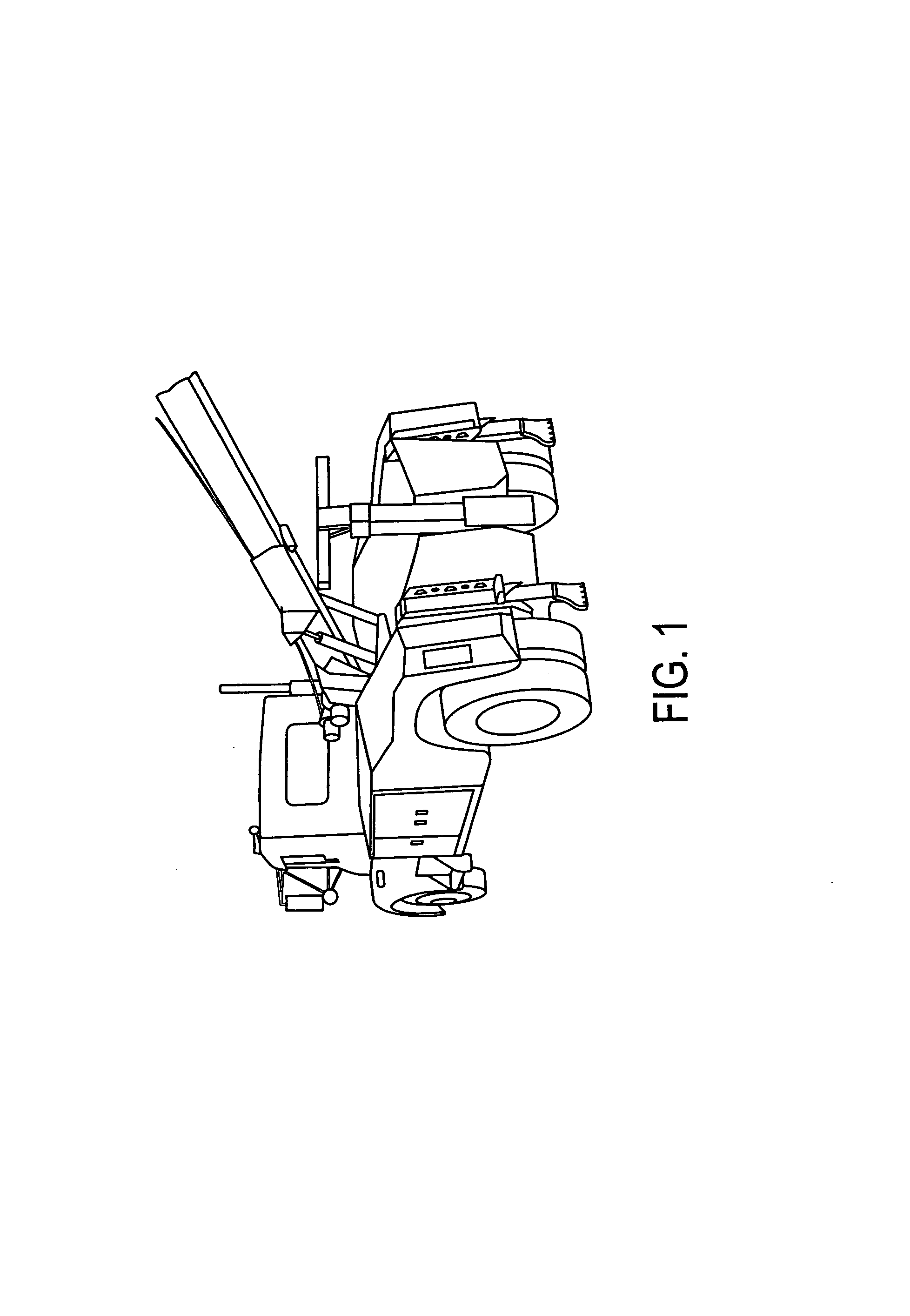
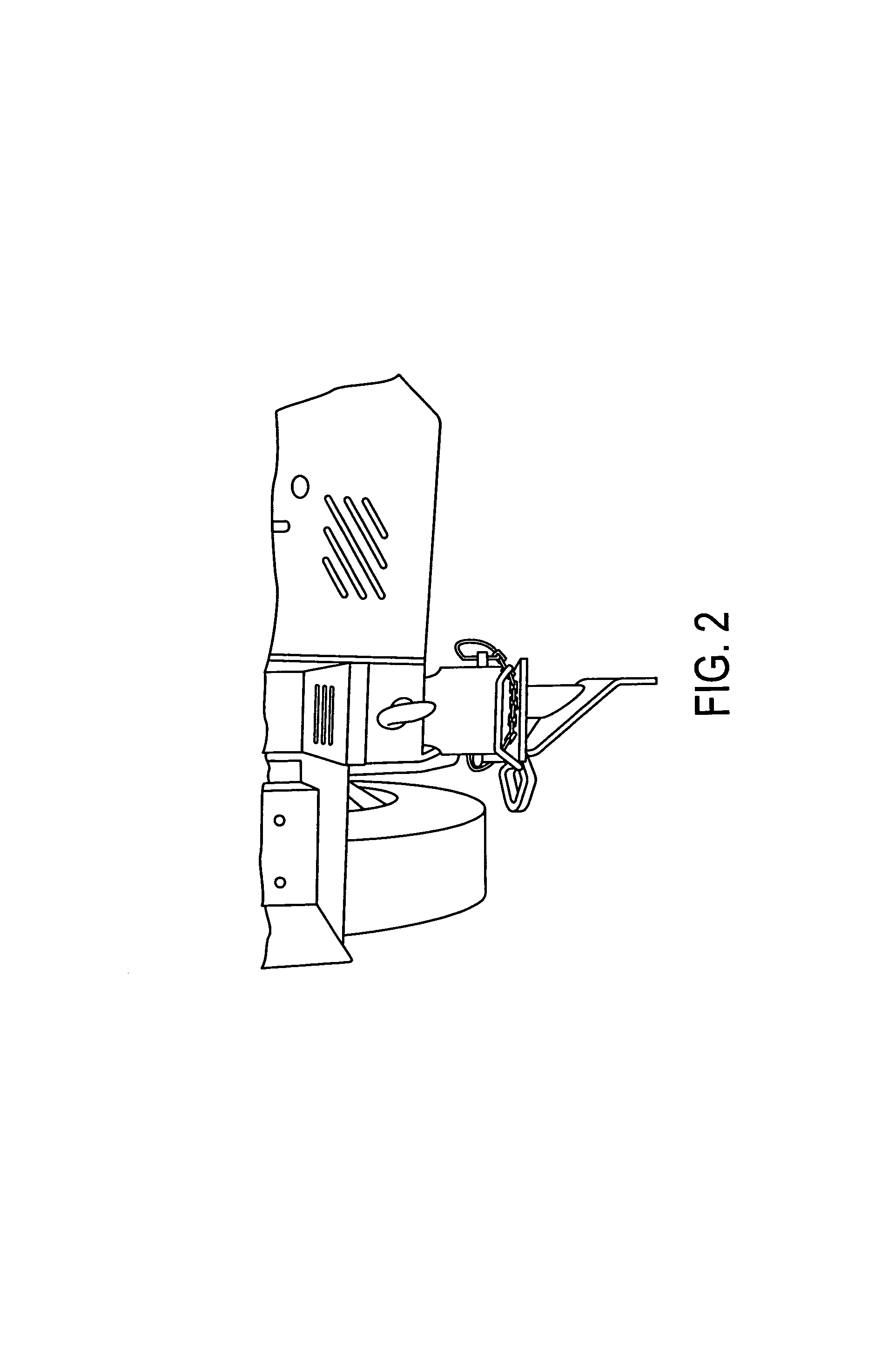
[0035]The present invention enables configuration of rescue vehicles that are capable of performing rescue operations on trapped vehicles while being positioned in the most stable position available. Hence, the rescue vehicle does not need to be repositioned based on the location of the trapped vehicle. Rather, the rescue vehicle is positioned in the most suitable location available and the recovery spades are oriented such that maximum traction is generated during the recovery operation. FIGS. 1–5 illustrate various configurations of the combination of the recovery spade of the present invention with a rescue vehicle. It should be noted that although one recovery spade is shown coupled to the rescue vehicle, a plurality of recovery spades can be used. It is preferred that at least two be used (one on each side of the rescue vehicle).

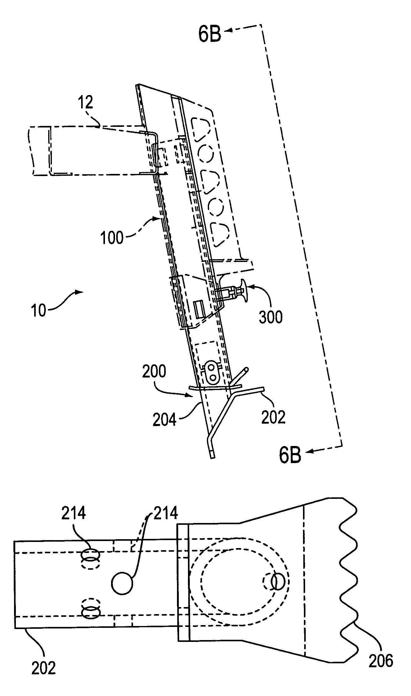
[0036]Turning to FIGS. 6a and 6b, one exemplary embodiment of the recovery spade 10 of the present invention will be discussed. FIG. 6a illustrates a s...


PUM


Abstract

A recovery spade that is adjustably coupled to a rescue vehicle to thereby maximize traction during rescue operations. The recovery spade includes an anchor blade and a hollow support member. The anchor blade includes a plurality of holes for selective connection to the support member at differing heights via a pin. The anchor blade further includes an anchor portion with teeth at one end for engaging the ground to effect the traction and coupling holes at the other end for selective connection to the anchor blade at differing angles.

Description

BACKGROUND OF THE INVENTION[0001]The present invention relates to rescue and rescue vehicles and, more particularly, to a recovery spade for maintaining the vehicle in a stationary position during rescue and recovery operations.[0002]During the course of normal activities, drivers often encounter hazards that often result in vehicular misfortunes. Such misfortunes often involve one or more vehicles being directed off a public and / or private road into a trench or furrow (i.e., a ditch). Once in the trench, the vehicle becomes trapped and is unable to escape on its own. Normally, a rescue vehicle must be provided to retrieve the trapped vehicle. Rescue vehicles are known by various other names, including “wrecker” rescue vehicle, towing vehicle, tow truck, etc.[0003]Rescue vehicles are commonly fitted with a crane member (or boom) that includes a winch and associated cable. The cable is secured to the trapped vehicle and the winch is activated to pull the trapped vehicle out of the tr...

Claims


Application Information

Patent Timeline
IPC IPC(8): B60S9/02B60P3/12B60S9/04
CPCB60P3/12B60S9/04
Inventor HUMPHRIES, DAVID F.
Owner JERR DAN
Learn More