Image forming apparatus

a technology of image forming apparatus and forming tube, which is applied in the field of image forming tube, can solve the problems of easy breakage of larger air bubbles, deterioration of printing quality, and influence of air bubbles on the detection of ink depletion, so as to achieve the effect of not deteriorating the detection accuracy of ink depletion

Active Publication Date: 2007-06-05
SHARP KK
View PDF7 Cites 3 Cited by
  • Summary
  • Abstract
  • Description
  • Claims
  • Application Information

AI Technical Summary

Benefits of technology

[0014]The present invention, in view of the aforementioned conventional problems, has an object of providing an image forming apparatus in which ink depletion detection accuracy is not deteriorated (maintained) even if an air bubble is created in an ink supplying path.

Problems solved by technology

However, in applying the negative pressure via a filter from the print head side (the ink spraying outlet side) in order to suck out the ink, there is a possibility that printing quality would be deteriorated if the air is sucked in from the print head side.
However, a larger air bubble is easy to break.
Further, in the art described in Japanese Publication of Unexamined Patent Application, Tokukai, No. 2002-36557, there is a problem that the air bubble gives influence on detection of ink depletion.
Moreover, in Japanese Publication of Unexamined Patent Application, Tokukai, No. 2002-67353, there is a problem that the second filter, which is finer than the first filter, produces a smaller air bubble, thereby deteriorating accuracy in detection of the ink depletion.

Method used


Image

  • Image forming apparatus
  • Image forming apparatus
  • Image forming apparatus

Examples


Embodiment Construction

[0049]With reference to FIGS. 1 to 25, the following describes one embodiment of the present invention.

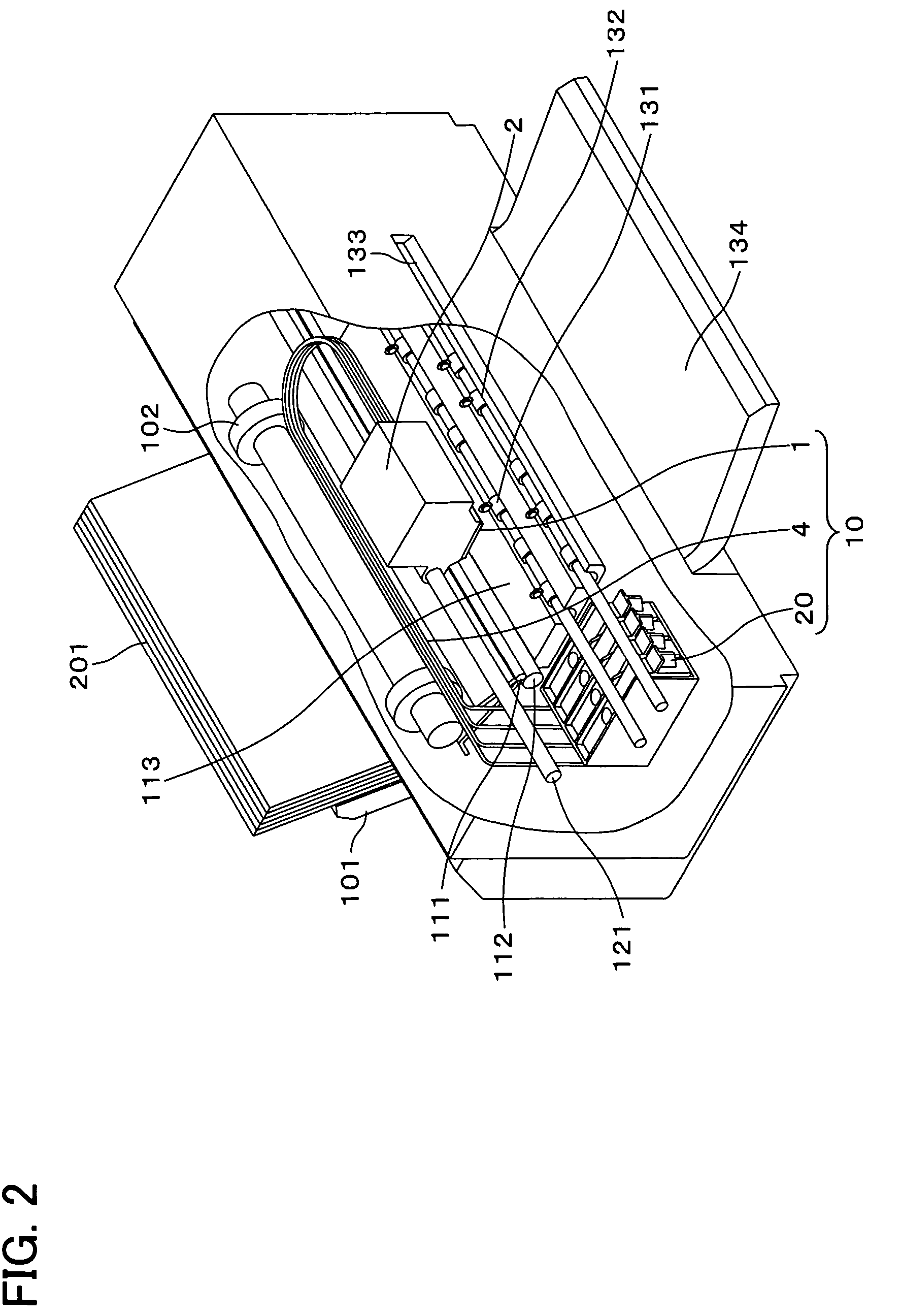
[0050]As shown in FIG. 2, an ink jet recording apparatus of the present embodiment functions as an image forming apparatus and includes a feeding section, a separating section, a conveying section, a printing section, and an ejecting section.

[0051]The feeding section, which includes a feeding tray 101 and a pickup roller 102, feeds recording sheets 201 in printing. When printing is not performed, the feeding section functions as a sheet storage for storing the sheets 201 therein.

[0052]The separating section supplies, sheet-by-sheet to the printing section, the sheets 201 fed by the feeding section. The separating section includes a feeding roller and a separator (neither is shown). The separating apparatus is so set that the friction between a sheet and a pad section, which is a point of contact with the sheet 201, is larger than the friction between the sheets 201. The feeding rol...


PUM


Abstract

An image forming apparatus in which ink depletion detection accuracy will not be deteriorated even if an air bubble is created in an ink supplying path. The image forming apparatus is provided with (a) an ink storage section for storing ink therein, (b) an ink supplying path for supplying, to a print head, the ink stored in the ink storage section, and (c) an electrode for detecting whether the ink is present or absent in the ink supplying path, an amount of the ink supplied into the ink supplying path being 1.0 cc or less per minute.

Description

[0001]This Nonprovisional application claims priority under 35 U.S.C. § 119(a) on Patent Application No. 2003 / 20895 filed in Japan on Jan. 29, 2003, the entire contents of which are hereby incorporated by reference.FIELD OF THE INVENTION[0002]The present invention relates to an image forming apparatus provided with an ink storage section for storing ink therein, particularly, to an ink jet recording apparatus as an image forming apparatus.BACKGROUND OF THE INVENTION[0003]The ink jet recording apparatus is an image forming apparatus for printing by jetting out (spray) ink on a sheet functioning as a recording sheet. The ink jet recording apparatus is generally provided with an ink cartridge including an ink tank. The ink is supplied from the ink cartridge to a print head. Then, the ink is jetted out from the print head onto the sheet.[0004]In using such ink jet recording apparatus, it is necessary to replace the ink cartridge when the ink in the ink cartridge runs out (depletes). Thu...

Claims


Application Information

Patent Timeline
Patent Type & Authority Patents(United States)
IPC IPC(8): B41J2/175B41J2/045B41J2/195
CPCB41J2/0451B41J2/04586B41J2/17566B41J2/17596B41J2/195
Inventor MATSUSHITA, MASAKINAKAMURA, HIROKAZUUENO, NAOZUMIYOSHIMURA, HISASHIGOTOH, TAKASHIISHII, HIROSHI
Owner SHARP KK
Why Eureka
Try Eureka