Multilayer plain bearing

a multi-layer, plain bearing technology, applied in bearing components, bearings, shafts and bearings, etc., can solve the problems of mechanical reworking of the gliding layer, particularly a material removal reworking, boring, and is impossible or possible, and the gliding layer's gliding properties will be significantly impaired

Inactive Publication Date: 2007-06-05
FEDERAL MOGUL DEVA
View PDF14 Cites 29 Cited by
  • Summary
  • Abstract
  • Description
  • Claims
  • Application Information

AI Technical Summary

Benefits of technology

[0007]The present invention has the object of making available a multi-layer plane bearing of the type give...

Problems solved by technology

The known and existing multi-layer plane bearings described have the disadvantage that as a rule, mechanical reworking of the gliding layer, particularly a material-removing reworking, such as for example broaching...

Method used


Image

  • Multilayer plain bearing
  • Multilayer plain bearing

Examples


Embodiment Construction

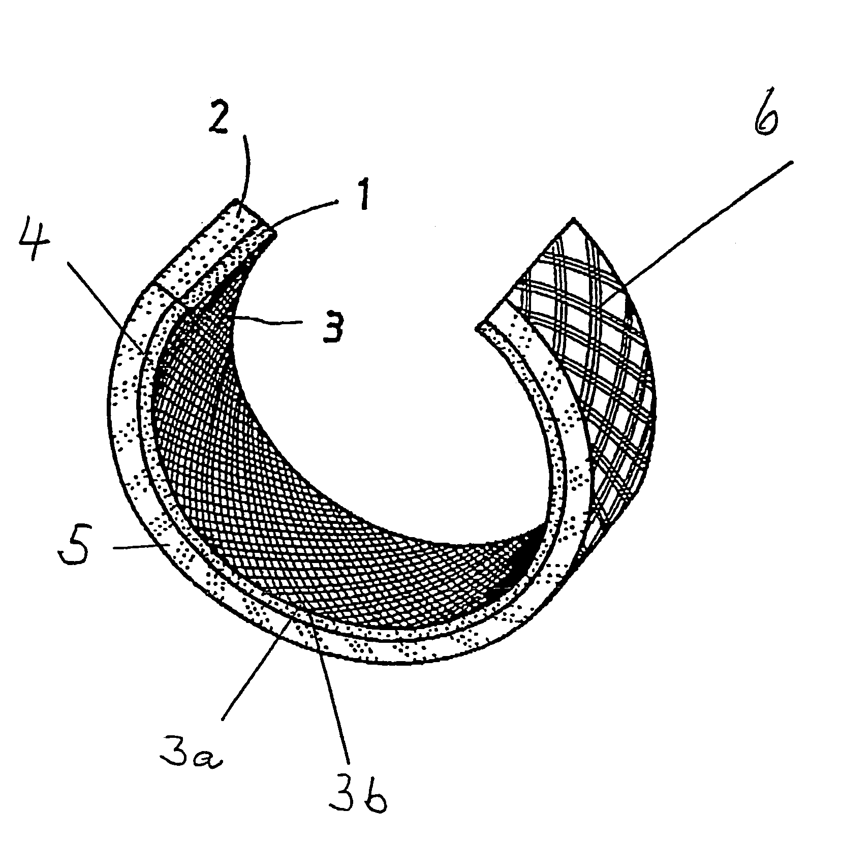
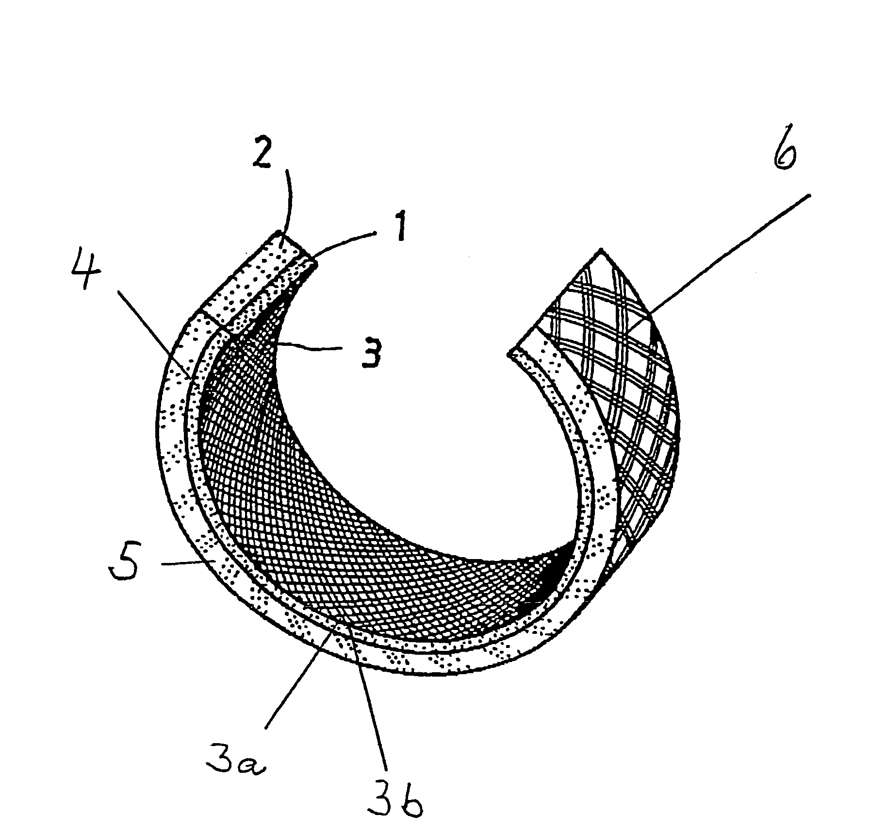
[0038]In the single FIGURE, a multi-layer plane bearing formed as a round sleeve is schematically and perspectively illustrated, in which the relative illustration of the round sleeve is only partial, in order to also show a sectional surface. Here the illustrated round sleeve exhibits an enclosed gliding layer 1 and a one-piece outer bearing layer 2 connected to it.

[0039]The gliding layer 1 includes an epoxy resin matrix 4 as well as a schematically drawn thread layer 3 encased in the epoxy resin layer 4. Here the thread layer 3 is formed from a multitude of individual threads, in which the threads 3a run in one direction, while the threads 3b are aligned in a second direction in such a way that the threads 3a form an angle of 90° relative to the threads 3b.

[0040]The threads 3a and 3b exhibit an identical thread construction.

[0041]Here each thread 3a or 3b possesses a primary thread component, consisting of a spun polytetrafluorethylene- / polyethersulfone mixed fiber with a Z-rotat...


PUM


Abstract

A multi-layer plane bearing has a bearing layer and a gliding layer connected to it. The gliding layer includes at least one thread layer treated with an epoxy resin. The thread layer is made up of a multitude of threads of at least one thread type arranged in a given pattern. Each thread includes at least one primary thread component made of spun PTFE/polyethersulfone mixed fiber yarn and at least one secondary component made of spun polyethersulfone fiber. There thread components are twisted in shaping the threads.

Description

TECHNICAL FIELD[0001]The present invention concerns a multi-layer plane bearing.[0002]Multi-layer plane bearings, also known as composite plane bearings, have been known for many years in various forms as machine elements for the transmission of power. As a rule, these plane bearings consist of at least two materials with differing mechanical properties, such that one material, which is generally the bearing layer, receives the power, while the other material, which is generally the gliding layer, assures the necessary gliding ability, especially under dry operation, i.e. without added liquid lubricants.[0003]The gliding layer of the known multi-layer plane bearings usually consists of a self-lubricating material that is embedded in a suitable plastic matrix, particularly in an epoxy resin. The self-lubricating materials used are all kinds of aromatic polyamides, carbon, aromatic polysulfones, also called polyethersulfones, aromatic polyimides, aromatic polyesterimides and / or polyte...

Claims


Application Information

Patent Timeline
IPC IPC(8): F16C33/28F16C33/04F16C33/20
CPCF16C33/04F16C33/201F16C33/28Y10S384/911
Inventor ROOS, UDOKRAFT, ERIK
Owner FEDERAL MOGUL DEVA
Why Eureka
Try Eureka