Grease cap for a constant velocity joint

a constant velocity joint and grease cap technology, which is applied in the direction of mechanical equipment, transportation and packaging, couplings, etc., can solve the problems of increasing the cost of the propeller shaft and constant velocity joint to unrealistic prices, prior art prop shafts encounter obstacles, and the width line is reduced. , the effect of increasing or decreasing the energy or for

Inactive Publication Date: 2007-06-05
GKN DRIVELINE NORTH AMERICA
View PDF21 Cites 48 Cited by
  • Summary
  • Abstract
  • Description
  • Claims
  • Application Information

AI Technical Summary

Benefits of technology

[0017]One advantage of the present invention is that it provides a novel cap for use in a collapsible constant velocity joint.
[0018]Still another advantage of the present invention is that the number of reduced width lines on the cap can vary thus creating a tunable cap for use in failing at a predetermined load during a crash event depending on design requirements.
[0019]Still another advantage of the present invention is that the frangible grease cap is sufficiently strong to not fail during handling of the joint or prop shaft or during assembly of the constant velocity joint and prop shaft into the vehicle, but is capable of breaking at a predetermined load during a crash event of the automotive vehicle.
[0020]Still another advantage of the present invention is the method of securing the grease cap to the outer race to allow for a predetermined axial load to dislodge the cap from the outer race.
[0021]Still another advantage of the present invention is that the grease cap for the collapsible constant velocity joint may be used in conjunction with other energy absorbing methods to further increase or decrease the energy or force being absorbed during a crash event and achieve the desired force vs. distance profile.
[0022]Yet another advantage of the present invention is that the frangible grease cap is capable of absorbing energy at multiple time intervals thus creating a delayed energy absorbing characteristic during a crash event for a vehicle.

Problems solved by technology

The ability of the prop shaft to collapse and telescope within itself will prevent the prop shaft from buckling which may lead to a penetration of the passenger compartment or damaging vehicle components in close proximity to the propeller shaft such as gas tanks, drive axles and other drive train components.
Some of the prior art propeller shafts will deform under certain loading conditions but many of these crash features that are designed into the propeller shaft are often complex and increase the cost of the propeller shaft and constant velocity joint to unrealistic prices.
Furthermore, the prior art prop shafts encounter obstacles when they are designed for relatively low collision or collapse forces because a strong robust propeller shaft is required at the same time for everyday use in modem day vehicles.
Prior art collapsible propeller shafts tend to absorb energy in a one time manner and once they have collapsed they will no longer perform any energy absorbing characteristics which may be needed to further protect the passenger compartment of the automotive vehicle during the crash event.

Method used


Image

  • Grease cap for a constant velocity joint
  • Grease cap for a constant velocity joint
  • Grease cap for a constant velocity joint

Examples


Embodiment Construction

)

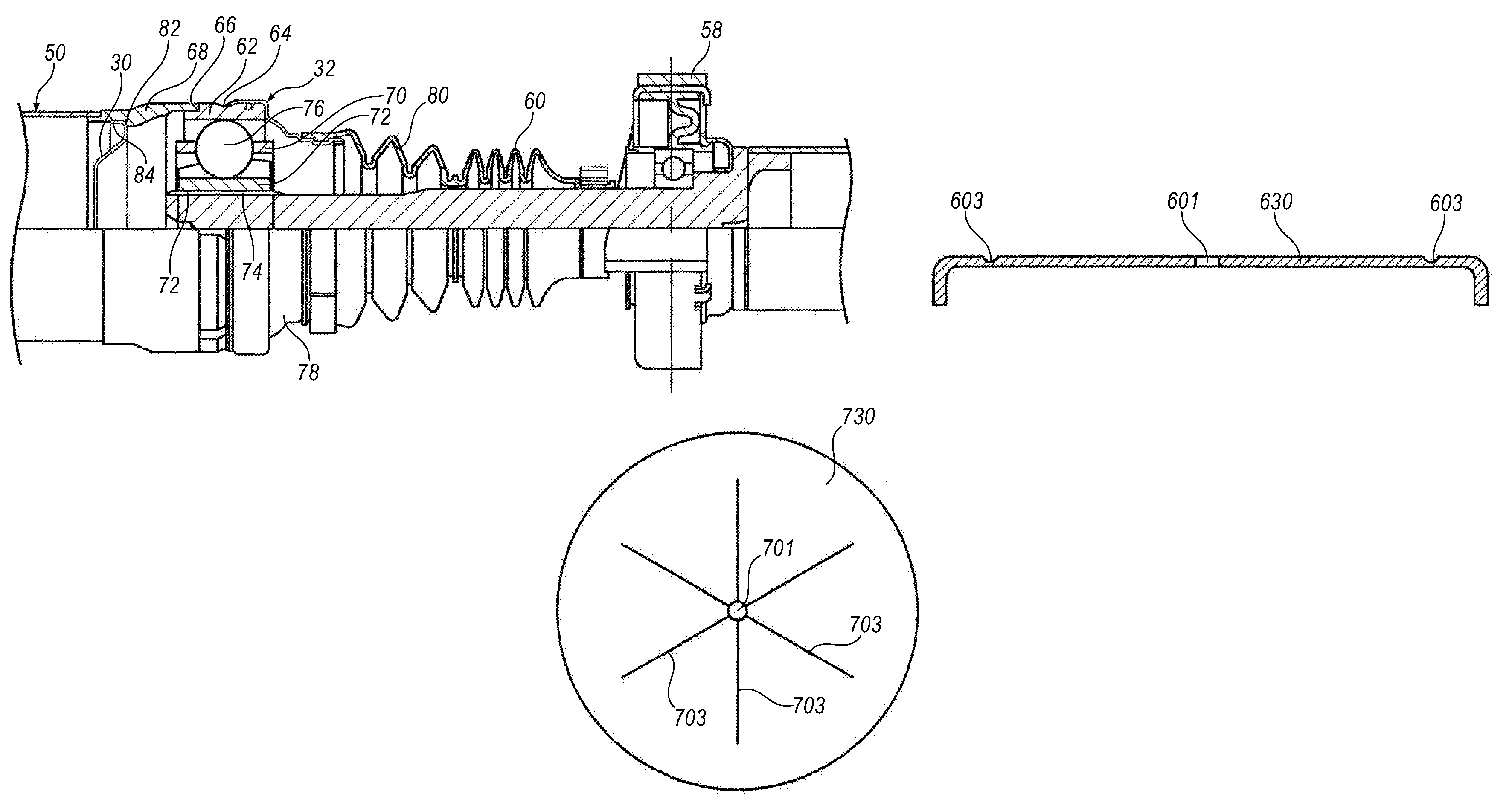
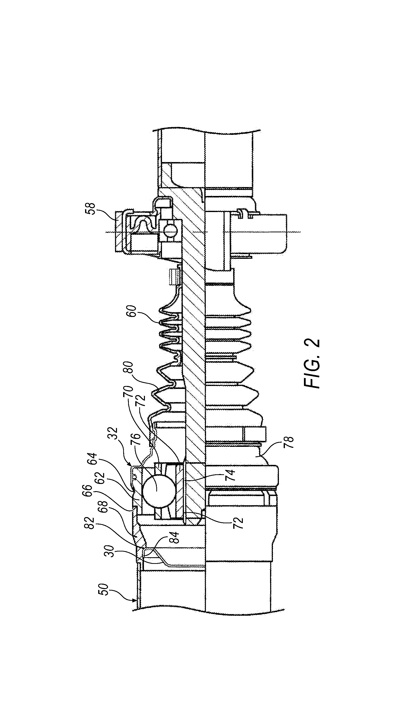
[0049]Referring to the drawings, a grease cap 30 according to the present invention is shown. The frangible grease cap 30 is for use on any known constant velocity joint 32 such as a plunging tripod, fixed tripod etc., which may be used in an all wheel drive, four wheel drive, front wheel drive or rear wheel drive vehicle. The constant velocity joint 32 includes a novel improved method of connecting the novel and improved grease cap 30 thereto.

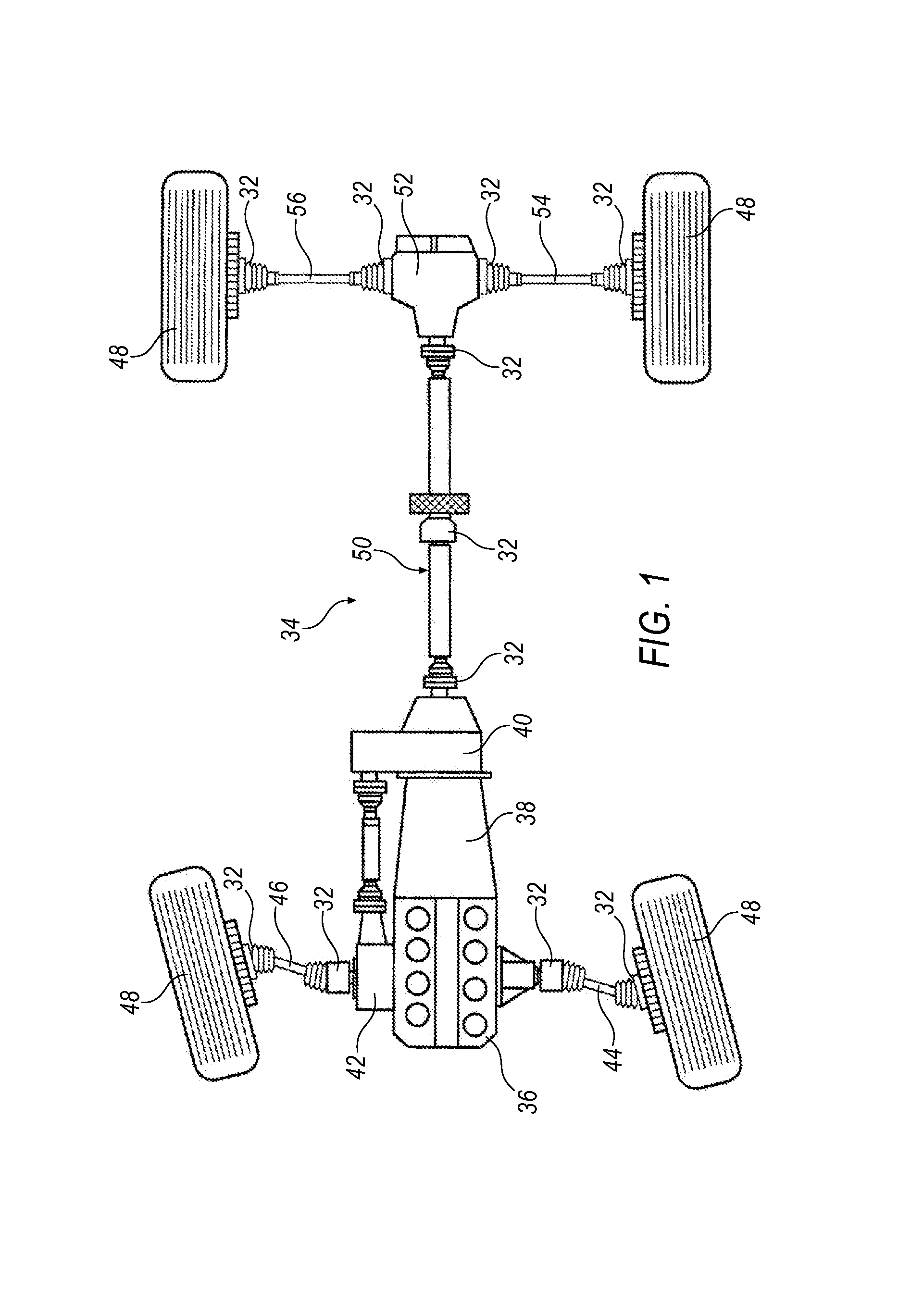
[0050]FIG. 1 shows a typical driveline 34 of an automotive vehicle. The driveline 34 is a typical all wheel drive vehicle driveline, however it should be noted that the constant velocity joints 32 of the current invention may also be used on rear wheel drive vehicles, front wheel drive vehicles, all wheel drive and four wheel drive vehicles. The driveline 34 includes an engine 36 that is connected to a transmission 38 and a power take off unit 40. The driveline includes a front differential 42 and includes a left hand front half shaft 44 and ...


PUM


Abstract

A frangible grease cap for use in a collapsible constant velocity joint. The frangible grease cap includes a body generally having a circular shape. The frangible grease cap includes an orifice through a center section of the body. The grease cap also includes at least one reduced thickness groove on a surface of the body of the constant velocity joint grease cap. The grease cap has a circumferential flange extending from an end thereof. The grease cap includes reduced thickness grooves having predetermined shapes which will peel or rupture when a predetermined axial load is applied thereto. The grease cap is secured to an inner surface of an outer race through any known securing method which also influences when the grease cap will fracture during or completely release during a crash event when a predetermined axial load is applied thereon.

Description

[0001]This application claims benefit of application Ser. No. 60 / 340,228 issued on Dec. 14, 2001.BACKGROUND OF THE INVENTION[0002]1. Field of the Invention[0003]The present invention generally relates to vehicle propeller shafts and constant velocity joints, and more particularly relates to a cap for use on a constant velocity joint that will release at a predetermined time in a crash event, and with a predetermined load, thus giving the constant velocity joint and the propeller shaft in a motor vehicle a specific crash behavior.[0004]2. Description of Related Art[0005]Propeller shafts (prop shafts) are well known in the art for use in vehicle propulsion systems. The prop shaft may be a multi-piece prop shaft or a solid / single-piece prop shaft depending on the type of drive train system on the vehicle therein. The prop shafts are generally used to transfer torque and rotational forces to the rear axle and rear wheels in all wheel drive, rear wheel drive and four wheel drive vehicles...

Claims


Application Information

Patent Timeline
Patent Type & Authority Patents(United States)
IPC IPC(8): F16D3/16F16C33/66F16C33/72F16D3/22
CPCF16C33/723F16D3/843F16D3/223F16D2300/06F16D2003/2232F16C2326/06
Inventor LYON, JAMES ALEXANDERLEONE, SALVATORE FILIPPOREIBSCHEID, DANIELKUCZERA, RAMON CHRISTOPHERLEE, J. TODD
Owner GKN DRIVELINE NORTH AMERICA
Why Eureka
Try Eureka