High performance field effect transistors comprising carbon nanotubes fabricated using solution based processing

a technology of carbon nanotubes and transistors, which is applied in the field of field effect transistors, can solve the problems of difficult production, limited application of organic-based devices, and inability to reproduce, and achieve the effects of facilitating dispersion, facilitating dispersion, and facilitating dispersion

Inactive Publication Date: 2007-06-05
GENERAL ELECTRIC CO
View PDF14 Cites 37 Cited by
  • Summary
  • Abstract
  • Description
  • Claims
  • Application Information

AI Technical Summary

Benefits of technology

[0064]In some embodiments, methods of making such FET devices comprise a number of steps. Referring to FIG. 3, the steps are: (Step 3001) dispersing carbon nanotubes (i.e., a mixture of semiconducting and metallic CNTs) in a solvent comprising a fractionating agent to form a dispersion; (Step 3002) centrifuging the dispersion to effect, with the aid of the fractionating agent, a fractionation of carbon nanotubes by electronic type into sediment and supernatant formed by the centrifuging, such that the supernatant becomes enriched in semiconducting carbon nanotubes; and (Step 3003) transferring the carbon nanotubes from the supernatant to a substrate to serves as active semiconducting material in a field effect transistor. It is an advantage of the present invention that such methods can be used in the fabrication of devices on plastic substrates and / or with plastic components.
[0065]Solvents suitable for dispersal of CNTs include, but are not limited to, N,N-dimethylformamide (DMF), chloroform (CHCl3), o-dichlorobenzene (ODCB), dichloromethane (CH2Cl2), benzene, toluene, xylenes, mesitylene, dimethylsulfoxide (DMSO), water, and combinations thereof. In some embodiments, a surfactant is used to facilitate the dispersion. In some embodiments, ultrasonication and / or some form of mechanical agitation is utilized to facilitate such dispersal. In some embodiments, heat is applied to facilitate dispersal.
[0066]Fractionating agents, according to the present invention, are species that complex or associate (in a non-covalent, non-destructive way) with the carbon nanotubes in the dispersion so as to effect a fractionation of the CNTs by type (i.e., metallic and semiconducting) when centrifuged, and provide for a supernatant that is enriched in semiconducting carbon nanotubes. In some embodiments, the fractionating agents are polymeric. In some embodiments these polymeric fractionating agents are amphiphilic. In some embodiments, the polymeric fractionating agents are conductive polymers. Suitable polymers include, but are not limited to, polythiophenes, polythiophene derivatives, poly(bithiophene-fluorenes), single-stranded DNA, and combinations thereof. Suitable polythiophenes include, but are not limited to, poly-3-hexyl-thiophene (P3HT), the structure of which is shown below.
[0068]In some embodiments, the fractionating agent assists in the de-bundling and dispersion of CNTs. CNTs, especially SWNTs, tend to agglomerate into bundles or ropes held together by van der Waals forces. In such embodiments, there is generally an energetic preference for CNT contact to the fractionating agent over CNT contact to itself. Such dispersion and fractionalization are described in commonly assigned co-pending U.S. patent application Ser. No. 10 / 925,312, filed Aug. 24, 2004.
[0069]In some embodiments, the fractionating agents comprise dendritic material. Such dendritic material may be attached to other polymeric material. Suitable dendritic material includes, but is not limited to, aliphatic ethers, aliphatic esters, aliphatic amines, aliphatic amides, aromatic ethers, aromatic esters, aromatic amines, aromatic amides, aromatic alkynes, phenylenes, aromatic alkenes, polyether carbamates, and combinations thereof.
[0070]Centrifugation typically is carried out in a centrifuge tube at a speed between about 1000 rpm and about 5000 rpm for a duration between about 1 minute and about 20 minutes. Such centrifugation typically yields sediment and supernatant, the sediment having gravitated to the bottom of the centrifuge tube and the supernatant being the liquid on top. It is in these two phases that a fractionation of the CNT mixture is realized: the sediment being enriched in metallic CNTs and the supernatant being enriched in semiconducting CNTs—relative to the starting material.

Problems solved by technology

However, such organic-based devices generally have limited application due to the low field effect mobilities (μ) realized in such devices and their poor reliability (e.g., reproducibility, variable threshold voltage, air stability, and processability).
While organic TFTs with field effect mobilities of 15 cm2 / Vsec have been reported with pentacene devices on treated silicon via evaporation, such results have not been reproducible (T. Kelly et al., ACS ProSpective Meeting, Thin-Film Electronics: Materials, Devices, and Applications, Jan. 25-28, 2004, Miami, Fla.).
Single crystals of organic materials have been shown to have mobilities as high as 10-15 cm2 / Vsec, but they are difficult to produce and still do not approach the mobility of 100 cm2 / Vsec anticipated to be required for high-performance devices and circuits (V. Sundar et al., “Elastomeric Transistor Stamps: Reversible Probing of Charge Transport in Organic Crystals,” Science, 2004, 303, 1644-1647).
Thus, high-performance field effect transistors (FETs) on plastic cannot be achieved with traditional organic materials, or, for that matter, with silicon, since in the latter case processing methods are limited to amorphous silicon.
Hence, the problem to be overcome is three-fold: limited processing capability, poor performance, and poor reliability of traditional organic TFTs.
While CNT transistors based on the use of a single CNT per channel are not currently commercializable due to expensive, unreliable, and uncontrollable processes, CNT transistors based on CNT networks have been prepared by growing CNT networks on silicon substrates at high temperatures, temperatures that are not compatible with plastic substrates.
Furthermore, such in situ growth of CNTs directly on substrates provides an uncontrollable mixture of semiconducting and metallic tubes such that on / off ratios of such devices are poor (Xiao et al., “High-Mobility Thin-Film Transistors Based on Aligned Carbon Nanotubes,” Appl. Phys. Lett., 2003, 83, 150-152).
Such in situ growth processes also tend to be low yield processes.
However, this process is not practical, as described therein, and the metallic CNTs still present can lead to short-circuited devices.
Such a transfer process is not practical or cost-effective, however, and growing tubes (individual or network) on plastic is not possible due to the high temperatures typically required.
However, as already mentioned, such single CNT devices are not practical and such methods still require isolation of semiconducting CNTs.
Such nanowires are limited, as they are typically produced in very low yield and readily oxidize in air.
Furthermore, inorganic nanowires suffer from trapped states on the nanowire surface and difficulties in doping.
Recently, this approach has been used to fabricate FETs comprising CNTs grown in situ on a device platform (L. An et al., “A Simple Chemical Route to Selectively Eliminate Metallic Carbon Nanotubes in Nanotube Network Devices,” J. Am. Chem. Soc., 2004, 126(34), 10520-10521), but such processing still requires high temperatures to generate the CNTs and leaves chemically-destroyed metallic CNTs in the device and this chemistry is acknowledged by the authors to not be completely selective.
Such resulting low-cost devices would allow their incorporation into articles of manufacture heretofore economically unrealizable.

Method used


Image

  • High performance field effect transistors comprising carbon nanotubes fabricated using solution based processing
  • High performance field effect transistors comprising carbon nanotubes fabricated using solution based processing
  • High performance field effect transistors comprising carbon nanotubes fabricated using solution based processing

Examples


example 1

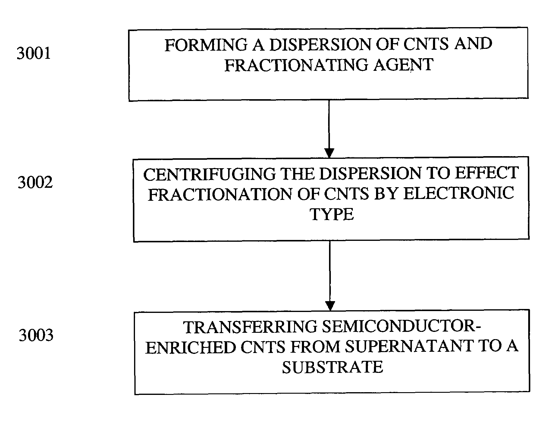
[0085]This Example serves to illustrate how CNTs can be selectively fractionated, according to some embodiments of the present invention, by type to yield CNT populations enriched in semiconducting CNTs.

[0086]CNTs used in this Example were HiPco-produced SWNTs of purified grade obtained from Carbon Nanotechnologies, Inc. (Houston, Tex.). Such purified tubes comprised metal impurities (predominantly Fe catalyst) in a range of 2-20 weight percent. These SWNTs typically have diameters in the range of 0.7-1.3 nm, lengths in the range of 1-1.5 microns, and an average electronic bandgap of around 0.8 eV.

[0087]Referring to FIG. 4, such fractionation typically requires three steps: (Step 4001) solubilization, (Step 4002) centrifugation, and (Step 4003) filtration. These steps are described in more detail below.

[0088](Step 4001) Solubilization: In vial 1, 0.1-1 mg / ml of purified SWNTs were partially dispersed in a solvent, most typically CHCl3, by sonicating the vial in a water bath for 5-30...

example 2

[0091]This Example serves to illustrate how Raman spectroscopy can be used to confirm fractionation of CNTs.

[0092]Evidence for the selective solubilization of semi-conducting SWNTs was obtained from Raman studies using a 514 nm laser light source, as shown in FIG. 5. The relative intensities of the bands in spectrum C (“centrifuge ppte,” i.e., post-centrifuge sediment, in FIG. 5) are significantly different from the intensities in the other three spectra shown in FIG. 5. This comparison suggests that P3HT partially separates SWNTs into semiconducting (sc)-enriched (supernatant) and metallic (met)-enriched (sediment) portions. Analysis of the Raman data was done in accordance with previous analyses (H. Katahura et al., “Optical Properties of Single-Wall Carbon Nanotubes,” Synthetic Metals, 1999, 103, 2555-2558; M. Dresselhaus et al., “Phonons in Carbon Nanotubes,” Advances in Physics, 2000, 49,705-814).

[0093]While not intending to be bound by theory, Table 1 is a summary and interpre...

example 3

[0097]This Example serves to illustrate a manner in which UV / vis / NIR spectroscopy can be used to confirm fractionation of CNTs.

[0098]In one particular embodiment, carbon nanotubes are dispersed by attaching at least one conjugated soluble polymer such as a polythiophene, polythiophene derivatives, a polyfluorene, or combinations thereof to the nanotube. In a particular embodiment, the conjugated soluble polymer is P3HT. While not intending to be bound by theory, the enhanced solubilization of some SWNTs by non-covalently attaching P3HT to SWNTs is shown by the UV / vis / NIR absorption spectra in FIG. 8. The UV / vis / NIR absorption spectra in FIG. 8 shows that P3HT has an affinity for the SWNTs, as evidenced by the 550-650 nm range (circled area FIG. 8). For comparative purposes, an UV / vis / NIR absorption spectrum of untreated SWNTs is shown in FIG. 9


PUM

PropertyMeasurementUnit
diametersaaaaaaaaaa
sizeaaaaaaaaaa
sizeaaaaaaaaaa

Abstract

The present invention is directed toward field effect transistors (FETs) and thin film transistors (TFTs) comprising carbon nanotubes (CNTs) and to methods of making such devices using solution-based processing techniques, wherein the CNTs within such devices have been fractionated so as to be concentrated in semiconducting CNTs. Additionally, the relatively low-temperature solution-based processing achievable with the methods of the present invention permit the use of plastics in the fabricated devices.

Description

CROSS-REFERENCE TO RELATED APPLICATIONS[0001]The present application is related to commonly assigned co-pending U.S. patent application Ser. No. 10 / 925,312, filed Aug. 24, 2004, incorporated by reference herein.TECHNICAL FIELD[0002]The present invention relates generally to methods for preparing field effect transistors (FETs), and more specifically to FETs comprising carbon nanotubes and to methods for preparing such FETs.BACKGROUND INFORMATION[0003]Organic-based electronic devices, in which the active semiconducting material is an organic compound (e.g., pentacene) or conjugated polymer (e.g., poly(3-alkylthiophene)), are attractive for their relatively inexpensive, low-temperature processability. However, such organic-based devices generally have limited application due to the low field effect mobilities (μ) realized in such devices and their poor reliability (e.g., reproducibility, variable threshold voltage, air stability, and processability). Different organic materials have b...

Claims


Application Information

Patent Timeline
Patent Type & Authority Patents(United States)
IPC IPC(8): H01L21/8238
CPCB82Y10/00H01L51/0048B82Y30/00H01L51/0545H01L51/0003H01L51/0036H01L51/0566Y10S977/742H01L51/0093H10K71/12H10K85/113H10K85/221H10K85/761H10K10/488H10K10/466
Inventor MALENFANT, PATRICK ROLAND LUCIENLEE, JI-UNGLI, YUNCICHA, WALTER VLADIMIR
Owner GENERAL ELECTRIC CO
Why Eureka
Try Eureka