Wiper blade for cleaning panes, in particular of a motor vehicle

a technology for cleaning panes and wiper blades, which is applied in the field of wiper blades, can solve the problems of inconvenient cleaning of wiper blades,

Active Publication Date: 2007-06-12
ROBERT BOSCH CORP
View PDF11 Cites 115 Cited by
  • Summary
  • Abstract
  • Description
  • Claims
  • Application Information

AI Technical Summary

Problems solved by technology

The triangle profile used requires a relatively large amount of material to manufacture the wind deflection strip, which is reflected in the costs of the wiper blade.
Moreover, the weight of the wiper blade becomes undesirably high.
Specifically, the increased mass to be accelerated in the pendulum wiping motion requires a more powerful drive system as well as a more expensive design of pendulum gear attached to it.
Furthermore, the action of the support element and of the wiper blade can be adversely affected by the bending stiffness, which depends on its profile, of a wind deflection strip thus formed.

Method used


Image

  • Wiper blade for cleaning panes, in particular of a motor vehicle
  • Wiper blade for cleaning panes, in particular of a motor vehicle
  • Wiper blade for cleaning panes, in particular of a motor vehicle

Examples


Embodiment Construction

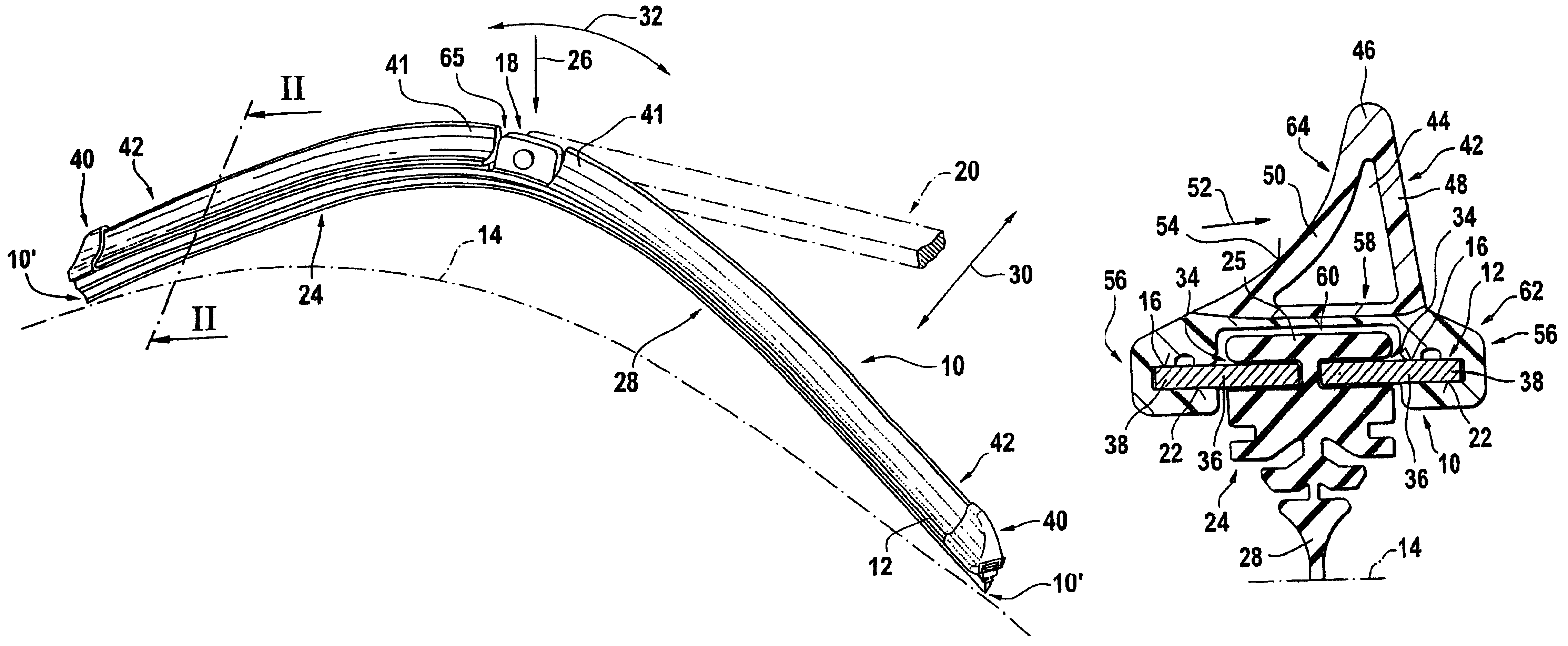
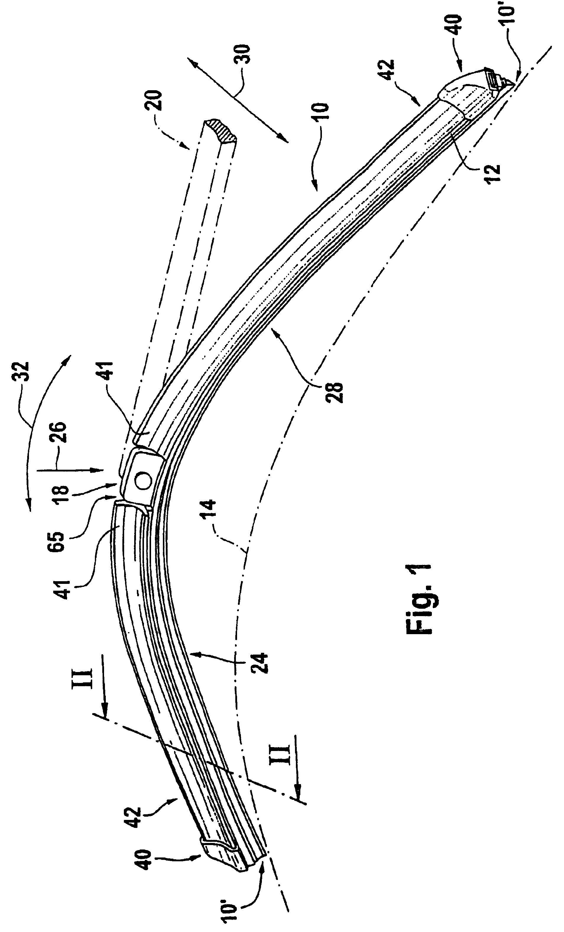
[0024]A wiper blade 10 shown in FIG. 1 has an elongated belt-shaped, flexible spring, one or more part support element 12 that is curved in the longitudinal direction in the un-loaded state. Located on the convex upper, or exterior, side of the belt 16 (FIGS. 1 and 2) of the support element facing away from the windshield 14 to be wiped there is a connector 18 attached to the center section of the support element, for example flat. By means of this connector, the wiper blade 10 can be removably connected to a driven wiper arm 20 that leads to the body of an automobile. Located on the concave lower, or inner, side of the belt 22 of the curved support element 12 that directly faces the windshield is an elongated elastic rubber wiper strip 24 that extends parallel to the longitudinal axis of the support element 12. At the free end of the wiper arm are mating connectors, which are not illustrated in more detail, that cooperate with the connector 18 of the wiper blade to form a hinge. Th...


PUM


Abstract

The invention relates to a wiper blade that cleans panes, in particular of motor vehicles. The wiper blade (10) comprises a strip-shaped, elongated, elastically resilient support element (12), the lower strip surface of which faces the pane (14) and is provided with an elongated, elastic wiper strip (24) running parallel to the longitudinal axis. The upper strip surface (16) of the element is provided with a wind deflector strip (42), which consists of an elastic material, extends in the longitudinal direction of the support element and has an oncoming stream surface (54) that faces the principal flow direction, (arrow 52), of the air stream. A particularly advantageous wiper blade, which is cost-effective to produce, can be achieved if the wind deflector strip, (when viewed in cross-section), comprises two limbs (48, 50), diverging from a common base (46) but mutually attached thereto, the free ends of said limbs facing the pane (14) and being supported on the wiper blade and if in addition, the oncoming stream surface (54) is configured on the external face of one limb (50) and the cross-sectional profile of the wind deflector strip is the same over its entire length.

Description

PRIOR ART[0001]In wiper blades with a spring-action support element, the support element is intended to guarantee as even a distribution of wiper blade pressure onto the windshield issued from the wiper arm as possible, and over the entire wipe field swept by the wiper blade. By appropriately bending the un-loaded support element into shape—the unloaded state being when only the two ends of the wiper blade sit against the windshield—the ends of the wiper strip, which sits completely against the windshield when the wiper blade is in operation, are pushed toward the windshield by the loaded support element, even if the radii of curvature of spherically curved vehicle windshields change with the wiper blade position. The curvature of the wiper blade must therefore be somewhat greater than the maximum curvature measured within the wipe field on the windshield to be wiped. This is because during wiping, the wiper strip, or its wiping lip that sits against the windshield, must be continuo...

Claims


Application Information

Patent Timeline
Patent Type & Authority Patents(United States)
IPC IPC(8): B60S1/38B60S1/04
CPCB60S1/381B60S1/3877B60S1/3879B60S2001/382B60S2001/3836
Inventor KRAEMER, GODELIEVEMAYER, JUERGEN
Owner ROBERT BOSCH CORP
Why Eureka
Try Eureka