Metering device for lubricant

a lubricant metering and lubricant technology, applied in the direction of liquid/fluent solid measurement, volume measurement, container, etc., can solve the problems of lubricant duct to be filled, and achieve the effect of increasing the driving torque and protecting the device from irreversible damag

Active Publication Date: 2007-06-12
PERMA TEC
View PDF29 Cites 37 Cited by
  • Summary
  • Abstract
  • Description
  • Claims
  • Application Information

AI Technical Summary

Benefits of technology

[0007]The invention is based on the object of specifying an electromechanically operated lubricant dispenser which is of simple construction and permits an exactly metered discharge of lubricant at high ejection pressure. The intention is for the lubricant store not to be acted upon by a compression-spring-loaded piston so as to avoid the risk of lubricant bleeding out.

Problems solved by technology

The movement of the piston inevitably causes the lubricant duct to be filled.

Method used


Image

  • Metering device for lubricant
  • Metering device for lubricant
  • Metering device for lubricant

Examples


Embodiment Construction

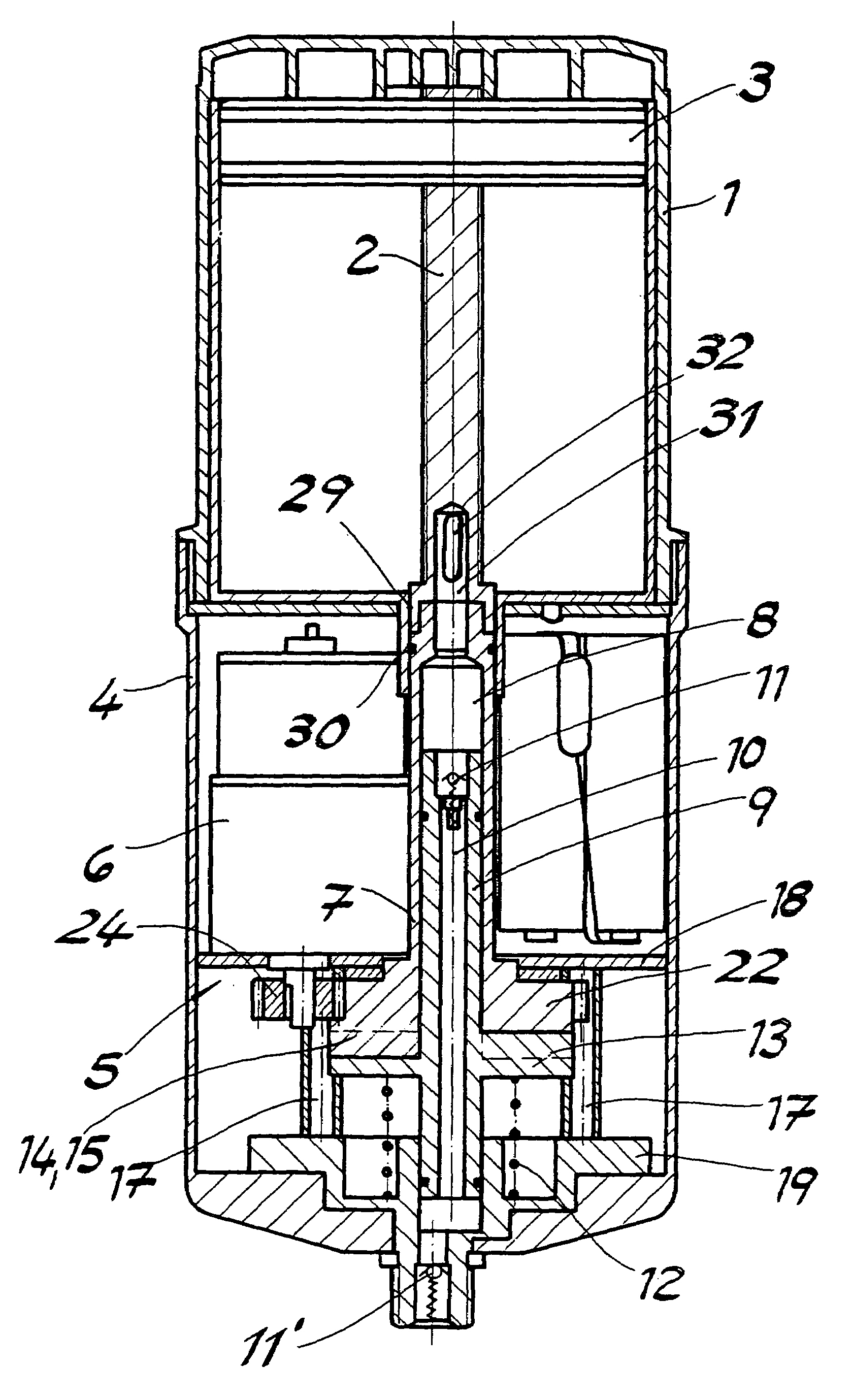
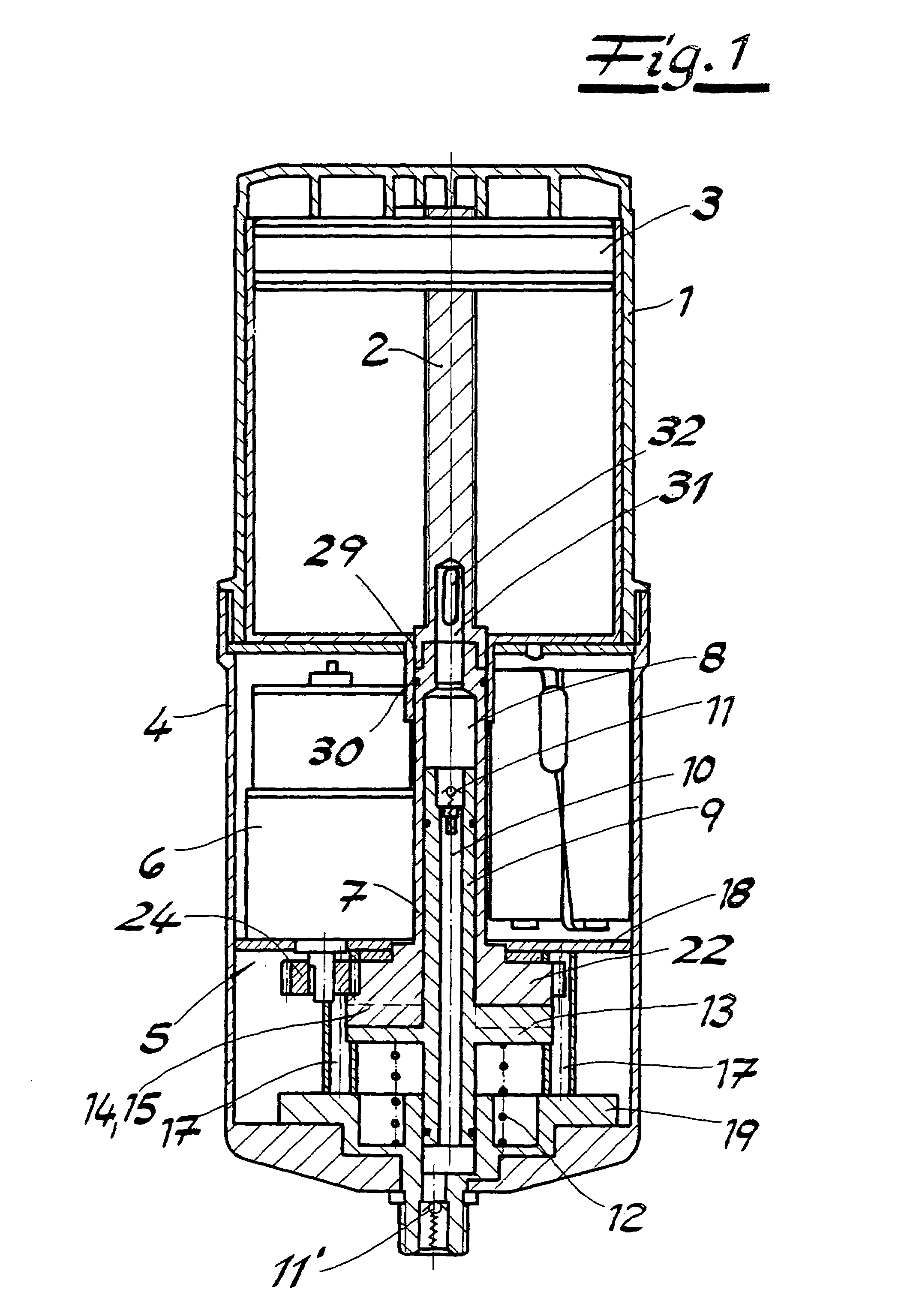
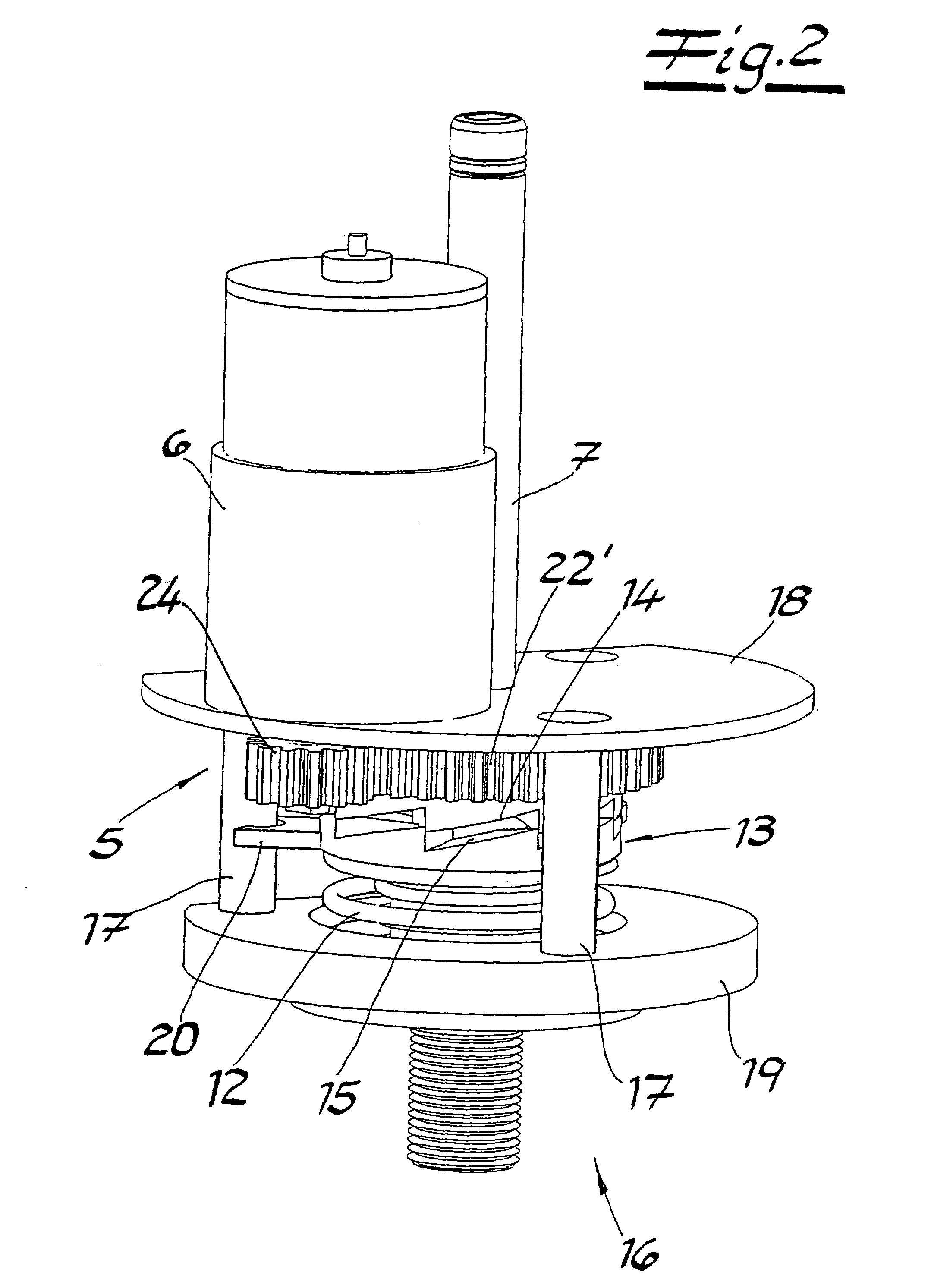
[0027]The metering device illustrated in FIG. 1 for lubricant has a lubricant reservoir 1 with a piston 3, which is arranged on a threaded spindle 2, and a drive head 4 having an electromechanical drive 5. The threaded spindle 2 is connected releasably to a drive shaft 7 of the drive head 4, the drive shaft being driven by an electric motor 6.

[0028]The drive shaft 7 contains a lubricant passage duct 8 which opens into the lubricant storage space of the lubricant reservoir 1. A ram 9 is inserted into the lubricant passage duct 8, said ram having an axial bore 10 with a nonreturn valve 11 on the inlet side, and a ram head 13 which is rotationally fixed in the drive head 4 and is supported in an axially movable manner on a compression spring 12. The ram head 13 bears under the effect of the compression spring 12 against a control surface 14 of the drive shaft 7. The control surface 14 and the associated contact surface 15 of the ram head 13 are designed as slotted-guide surfaces which,...


PUM


Abstract

The invention relates to a metering device for lubricant having a lubricant reservoir (1), a piston (3), which is arranged on a threaded spindle (2), within the lubricant reservoir and a drive head 4, which has a drive shaft (7) connected to the threaded spindle (2) and an electromechanical drive (5) for actuating the drive shaft. The drive shaft (7) contains a lubricant passage duct (8) which opens into the lubricant storage space of the lubricant reservoir. A ram (9) is inserted into the lubricant passage duct (8) of the drive shaft, said ram having an axial bore (10) with a nonreturn valve (11) on the inlet side, and also a ram head (13) which is arranged in a rotationally fixed manner and is loaded by a compression spring (12). The ram head (13) bears under the effect of the compression spring (12) against a control surface (14) of the drive shaft (7). The control surface (14) and the associated contact surface of the ram head (13) are designed as slotted-guide surfaces which, when the control surface (14) rotates, bring about stroke movements of the ram (9), said movements conveying lubricant through the bore (10) in the ram (9) to a lubricant outlet at the end of the ram.

Description

CROSS REFERENCE TO RELATED APPLICATIONS[0001]Applicants claim priority under 35 U.S.C. §119 of GERMAN Application No. 102 27 496.7 filed on Jun. 19, 2002. Applicants also claim priority under 35 U.S.C. §365 of PCT / EP02 / 08977 filed on Aug. 10, 2002. The international application under PCT article 21(2) was not published in English.BACKGROUND OF THE INVENTION[0002]1. Field of the Invention[0003]The invention relates to a metering device for lubricant having a lubricant reservoir, a piston, which is arranged on a threaded spindle, within the lubricant reservoir and a drive head, which has a drive shaft connected to the threaded spindle and an electromechanical drive for actuating the drive shaft.[0004]2. The Prior Art[0005]In an embodiment known from EP-A 0 845 631, the electromechanical drive has a threaded spindle which is driven by a geared motor. The lubricant reservoir is provided with an outlet opening for lubricant which is ejected by a movement of the piston. The build-up of pr...

Claims


Application Information

Patent Timeline
Patent Type & Authority Patents(United States)
IPC IPC(8): F16N27/00F16N11/08
CPCF16N11/08
Inventor WEIGAND, MICHAELSCHEIT, BERNDBRAND, STEFANHILDENBRAND, THOMAS
Owner PERMA TEC
Why Eureka
Try Eureka