Microfluidic device with network micro channels

a microfluidic device and microchannel technology, applied in the direction of fluid speed measurement, diaphragms, immobilised enzymes, etc., can solve the problems of inability to connect micro channels belonging to different networks in parallel, and the limitations of microfluidic devices

Inactive Publication Date: 2007-06-12
NATIONAL TSING HUA UNIVERSITY
View PDF5 Cites 59 Cited by
  • Summary
  • Abstract
  • Description
  • Claims
  • Application Information

AI Technical Summary

Benefits of technology

[0008]The second objective of the present invention is to immobilize a reagent on a plurality of sub-channels that are parallel in longitudinal direction in light of the difference in the width of the micro channels, so that the reagent may not overflow into the next main channel that is perpendicular to and connected to the sub-channels to cause cross contamination.
[0009]The third objective of the present invention is to divert a reagent from a main channel to sub-channels that are perpendicularly connected to the main channel, then make the reagent flow into another main channel connected to the other end of the sub-channels. As a result, the flow of the fluid is always kept under control, so that the fluid can run at a constant speed or a variable speed.

Problems solved by technology

In general, microfluidic devices are restricted by their fabrication method to such an extent that they have only two-dimensional micro channels, thus it is impossible to connect micro channels that belong to different networks in parallel.
Hence, these microfluidic devices have their limitations, as far as the scope of their applications and their operating methods are concerned.

Method used


Image

  • Microfluidic device with network micro channels
  • Microfluidic device with network micro channels
  • Microfluidic device with network micro channels

Examples


Embodiment Construction

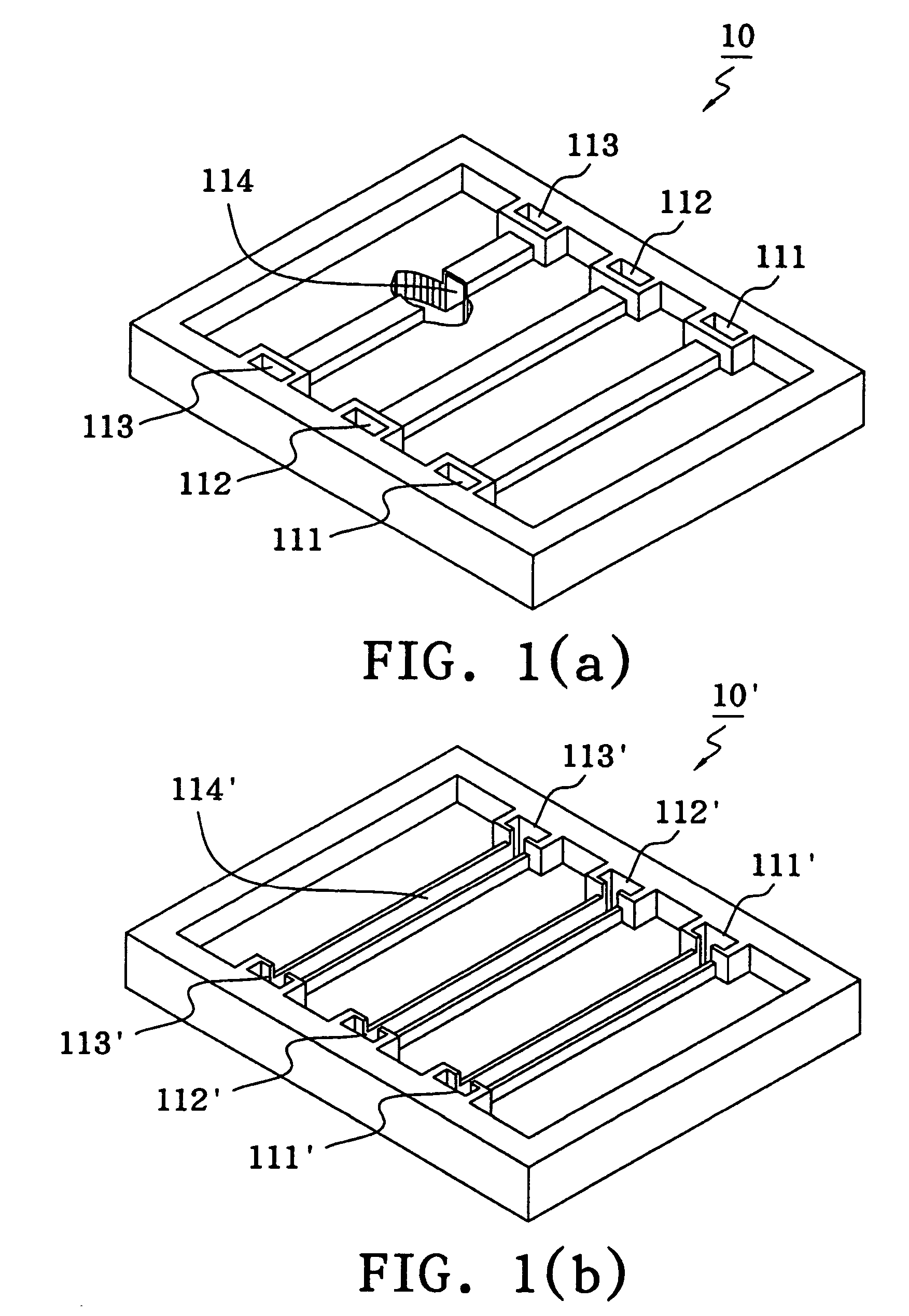
[0023]FIG. 1(a) is a perspective schematic diagram of the closed sample diversion layer of the microfluidic device in accordance with the present invention. A sample diversion layer 10 made of polymer has both of its sides equipped with three sample dropping entrances 111, 112 and 113 each, allowing any samples to be tested to reach the channels inside. For instance, if a sample is dropped into the dropping entrance 111, the sample drops will pass through an embedded sample channel 114. Furthermore, it is also feasible to design an open sample diversion layer 10′ as shown in FIG. 1(b), wherein each of the three sample dropping entrances 111′, 112′ and 113′ has a sample channel 114′ connected to it, and the sample channels 114′ have become open channels in contrast with the embedded sample channel 114.

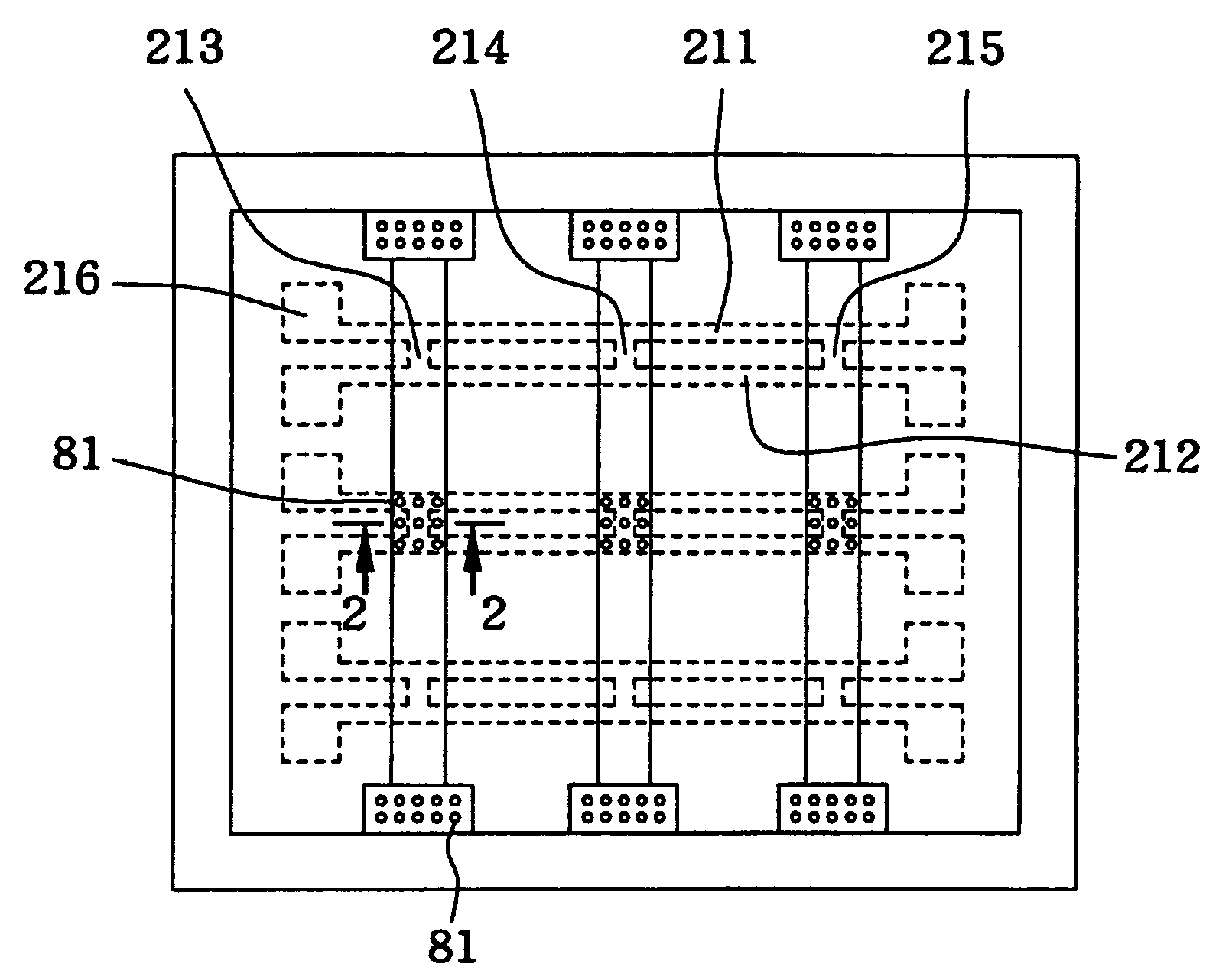
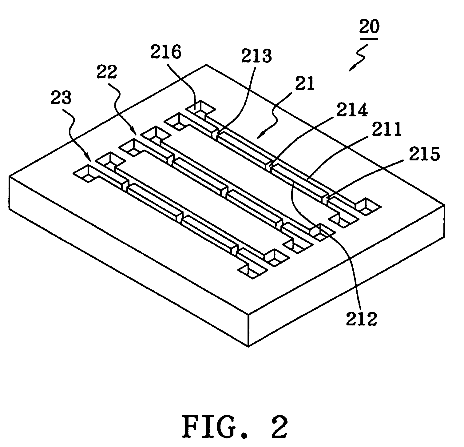
[0024]In addition, a reagent immobilization layer 20 is provided underneath the sample diversion layer 10. Three independent, but similar, H-shaped micro channels 21, 22 and 23 are prov...


PUM

PropertyMeasurementUnit
inner diameteraaaaaaaaaa
widthsaaaaaaaaaa
widthaaaaaaaaaa

Abstract

A microfluidic device has a plurality of H-shaped micro channels not connected to each other and formed on a substrate. Each of the H-shaped micro channels comprises two main channels separately placed on two opposite sides in parallel and a plurality of sub-channels perpendicularly connected to the two main channels. The present invention is designed in such a way that various reagents dropped into different H-shaped micro channels are immobilized on respective sub-channels because of the different widths of the main channel and sub-channel. Afterwards the reagents are coated with a layer of polymer. The polymer has a porous structure that allows the passage of any sample to be tested. Finally, a plurality of upper channels parallel to one another are directly fabricated in the polymer, or in another layer of polymer stacked on the previous polymer.

Description

BACKGROUND OF THE INVENTION[0001]1. Field of the Invention[0002]The present invention relates to a microfluidic device with network micro channels, and more particularly, to a microfluidic device applicable to biomedical analyses.[0003]2. Description of the Related Art[0004]Microfluidic devices integrated with biochips are getting more and more popular lately, because they provide better operational ways for biological or medical syntheses and analyses. Microfluidic devices are characterized by small size and an automatic diversion function, thus they have plenty of advantages, namely fewer amounts of reagents, miniaturization, fast sensing response, good integration, etc. They minimize manual operations, save reagents and rapidly process voluminous biological data transmitted in parallel, compared with conventional biomedical analytical methods.[0005]By a microfluidic device, it means infusing microliters, or even nanoliters, of liquid into a substrate with micro channels, and maki...

Claims


Application Information

Patent Timeline
Patent Type & Authority Patents(United States)
IPC IPC(8): G01N27/327B01L3/00G01N27/333B81B1/00G01N33/487
CPCB81B1/002G01N27/3271B01L3/5027B81B2201/0214B81B2201/058
Inventor TSENG, FAN-GANGLIN, KUANG-HUAHSU, HUI-TING
Owner NATIONAL TSING HUA UNIVERSITY
Why Eureka
Try Eureka