Lighted switch device

a technology of lighted switch and light guide, which is applied in the direction of contact mechanism, instruments, other domestic objects, etc., can solve the problems of reduced light emission, difficult light diffusion towards the emission surface, and non-uniform light guid

Active Publication Date: 2007-06-12
ALPHA +1
View PDF13 Cites 97 Cited by
  • Summary
  • Abstract
  • Description
  • Claims
  • Application Information

AI Technical Summary

Benefits of technology

[0009]An object of the present invention is to provide a lighted switch device capable of uniformly illuminating a key top or a periphery thereof so that the key top position can be recognized even in darkness.

Problems solved by technology

However, in the lighted switch structure as described in Japanese Patent Laid-Open No.2004-146260, because the distance from the LEDs to the emission surface is relatively short, it is difficult to diffuse the light towards the emission surface, and hence the emission surface tends to be one spot illumination.
Conversely, if a light diffusion material is introduced in the lighting part to achieve increased light diffusion efficiency, there is a problem that the amount of light emission is reduced.
Furthermore, in the keyhole illumination device as described in Japanese Utility Model Laid-Open No.S62-137972, the device is structured to indicate the position of the keyhole in darkness, however, there is a problem that the light becomes non-uniform in the light guide, because the light source is attached to a portion of the light guide.
Therefore, in this device, the structure makes it difficult for light emitted from the light source to go round to the opposite side of the light source.

Method used


Image

  • Lighted switch device
  • Lighted switch device
  • Lighted switch device

Examples


Embodiment Construction

[0018]Preferred embodiments of the present invention will be explained in detail with reference to the accompanying drawings below.

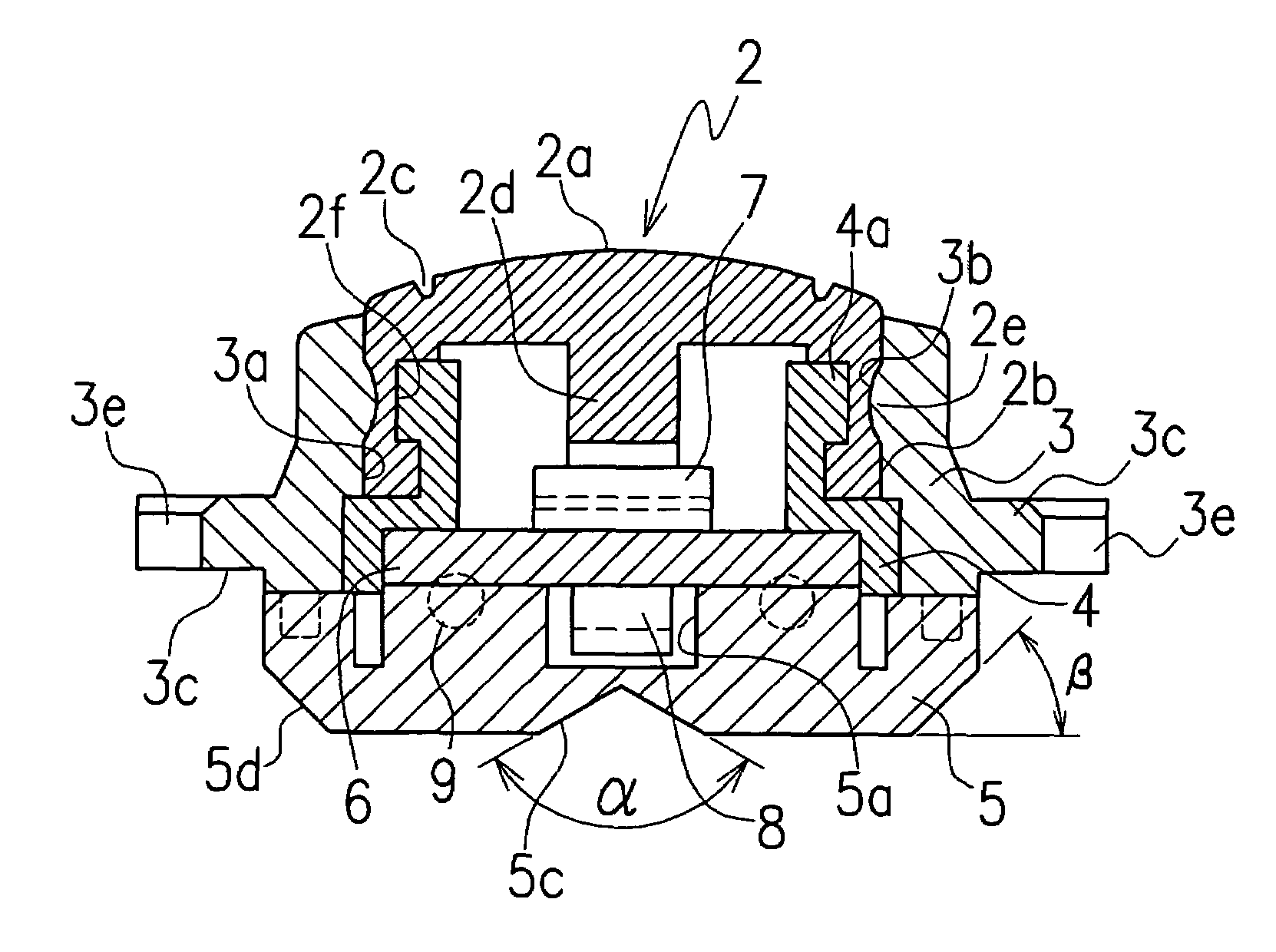
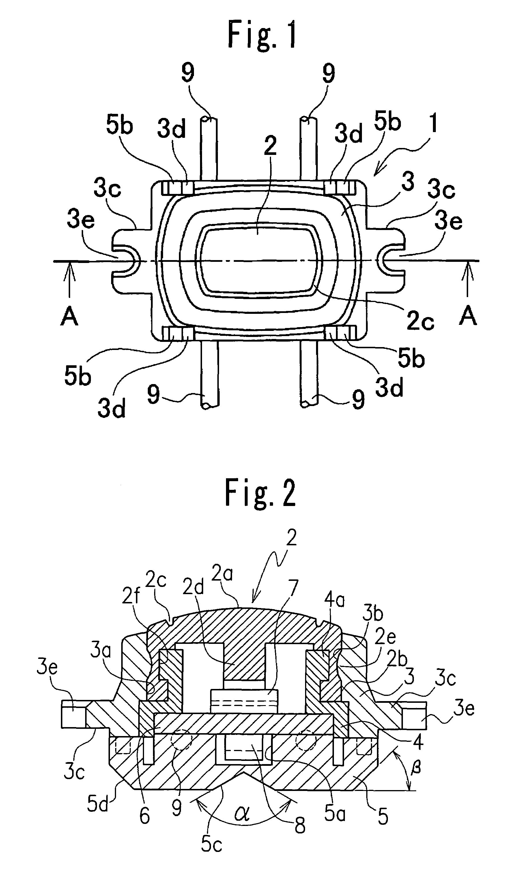
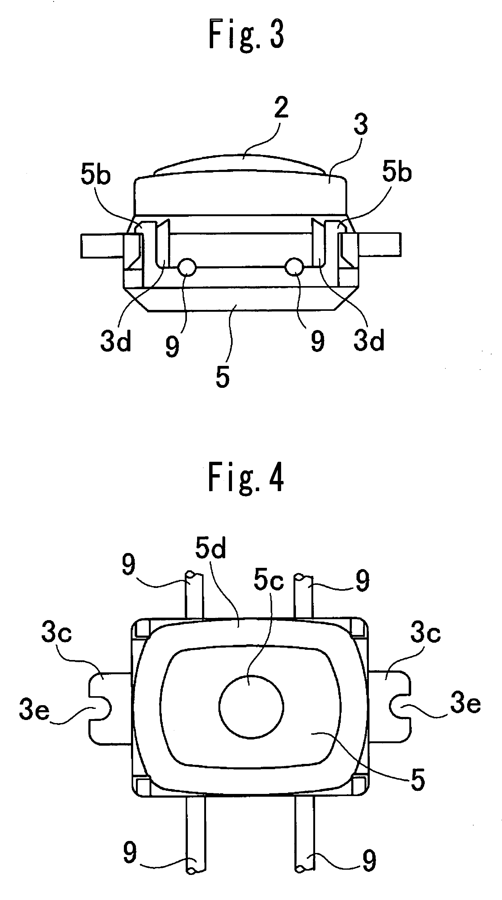
[0019]FIGS. 1 to 4 illustrate one embodiment of a lighted switch device 1 according to the present invention. The lighted switch device 1 includes a substrate 6, as shown in FIG. 2. A switch 7 is disposed on a first surface, for example, an upper surface, of the substrate 6 and a light source, for example, an LED 8 is disposed on a second surface, for example, a lower surface of the substrate 6 (see FIG. 2). The switch 7 is attached to a central wiring pattern (not shown) provided on the upper surface of the substrate 6 and the LED 8 is attached to a central wiring pattern (not shown) provided on the lower surface of the substrate 6. The switch 7 and the LED 8 are disposed on a central axis of the lighted switch device 1 A key top 2 is disposed above the switch 7 to operate the switch 7. The key top 2 is made of a resilient material such as silicon, for ...


PUM


Abstract

A lighted switch device, comprising a substrate, a switch provided on a first surface of the substrate, a light source provided on a second surface of the substrate, a key top to press the switch, and a light guide mechanism to guide light emitted from the light source to the key top or a periphery of the key top, the light guide mechanism including a first light guiding member to hold the key top and a second light guiding member disposed to surround the light source, the light emitted from the light source being guided through the second light guiding member to the first light guiding member holding the key top.

Description

CROSS-REFERENCE TO THE RELATED APPLICATION[0001]This application is based on and claims priority from Japanese Patent Application No. 2004-280751 filed on Sep. 27, 2004, the disclosure of which is incorporated herein by reference in its entirety.BACKGROUND OF THE INVENTION[0002]1. Field of the Invention[0003]The present invention relates to a lighted switch device used in in-car instruments, electric home appliances, front doors or equipments and apparatus expected to be used in darkness.[0004]2. Description of Related Art[0005]One known conventional lighted switch device used in meters of automobiles includes a press button, a lighting part provided on the press button, and a plurality of LEDs disposed on a wiring board, and the device is configured to guide light emitted from the LEDs through the lighting part to an emission surface provided on a top portion of the press button (for reference, see Japanese Patent Laid-Open No.2004-146260, FIG. 3 and paragraphs 0016 to 0022).[0006]...

Claims


Application Information

Patent Timeline
Patent Type & Authority Patents(United States)
IPC IPC(8): H01H9/00
CPCH01H13/023H01H2219/056H01H2219/06H01H2219/062H01H2219/0622H01H2231/012H01H9/161G02B6/4201H01H2219/036H01H2217/018
Inventor TOYAMA, YASUNORI
Owner ALPHA
Why Eureka
Try Eureka