Method and system for dynamically assigning domain identification in a multi-module fibre channel switch

a multi-module, domain-based technology, applied in the field of network systems, can solve the problem that current fiber channel standards do not provide a mechanism for combining multiple switch modules

Active Publication Date: 2007-06-12
MARVELL ASIA PTE LTD
View PDF58 Cites 48 Cited by
  • Summary
  • Abstract
  • Description
  • Claims
  • Application Information

AI Technical Summary

Problems solved by technology

Current Fiber Channel standards do not provide a mechanism to combine multiple switch modules into one switch.

Method used


Image

  • Method and system for dynamically assigning domain identification in a multi-module fibre channel switch
  • Method and system for dynamically assigning domain identification in a multi-module fibre channel switch
  • Method and system for dynamically assigning domain identification in a multi-module fibre channel switch

Examples


Embodiment Construction

[0039]Definitions:

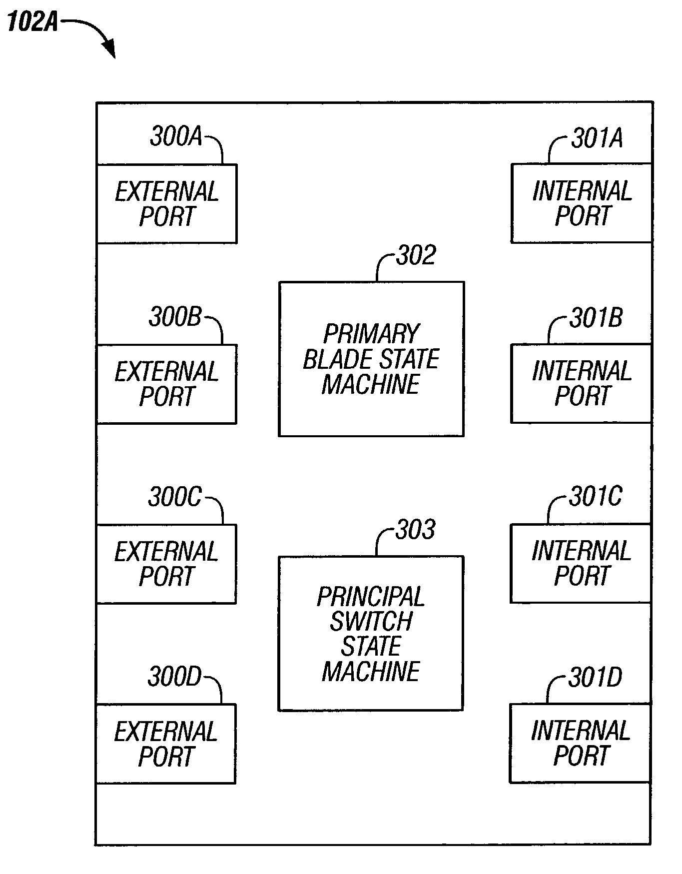
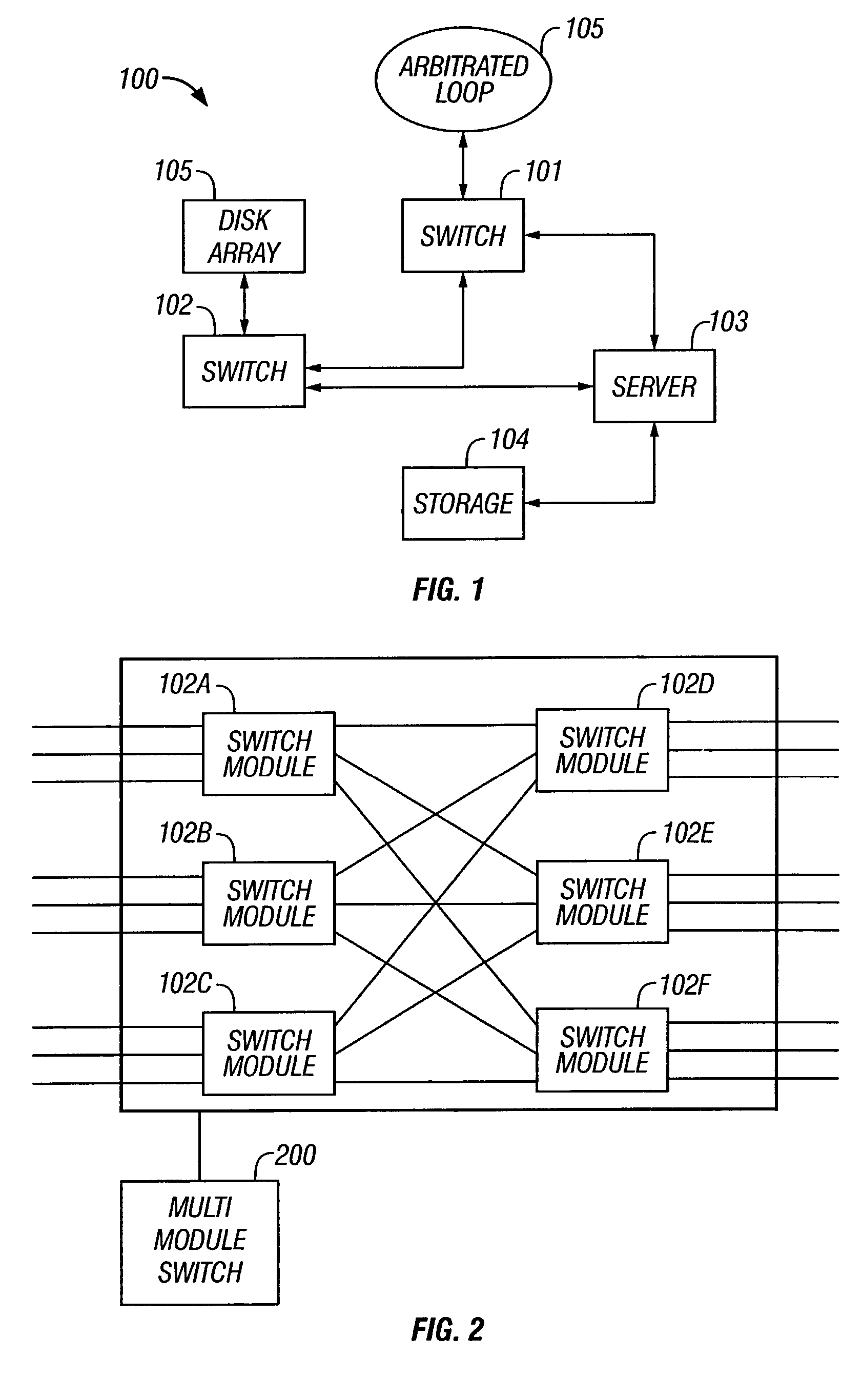
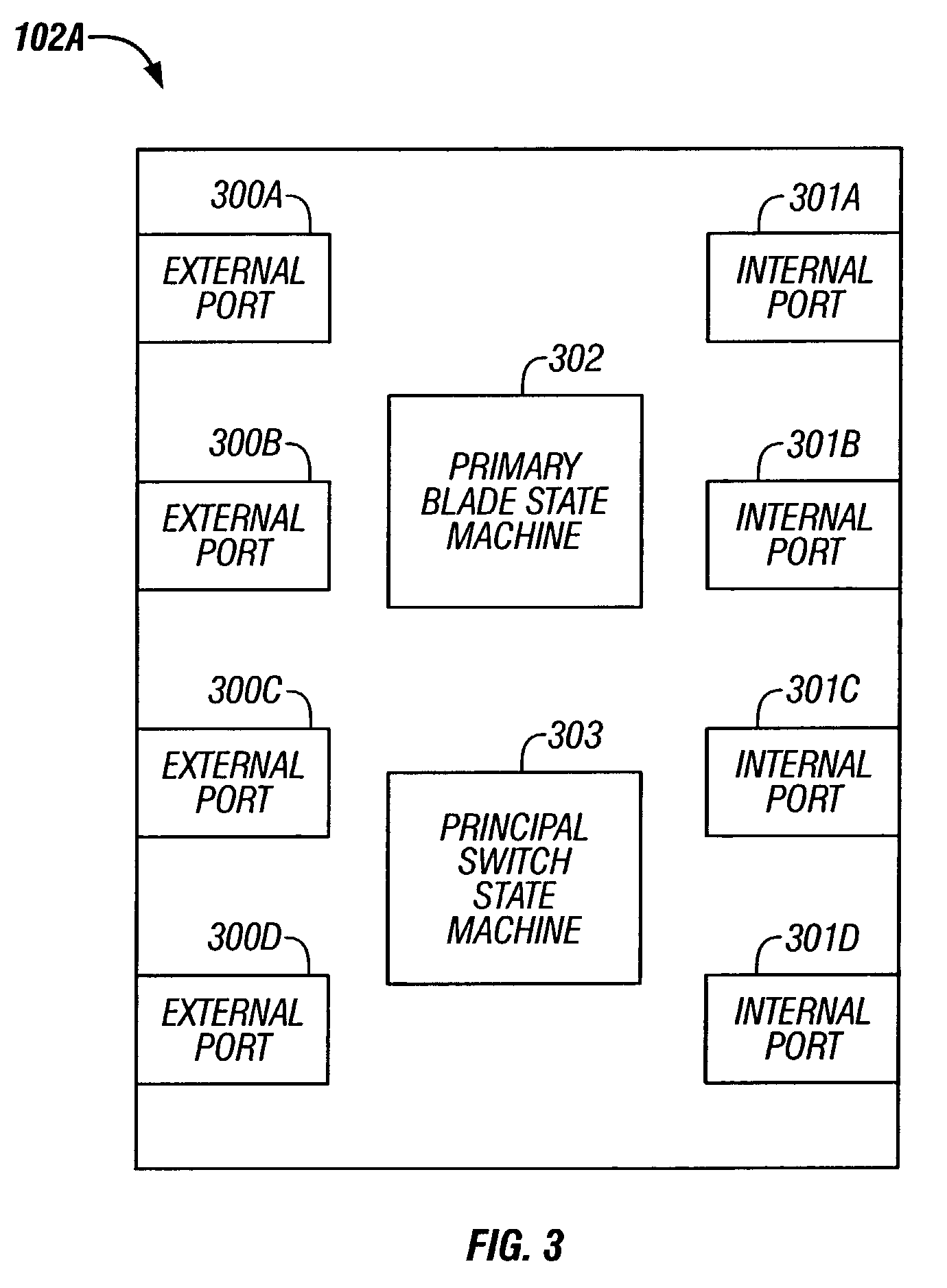
[0040]The following definitions are provided as they are typically (but not exclusively) used in the fibre channel environment, implementing the various adaptive aspects of the present invention.[0041]a. “Blade”: A module in a multi-module fibre channel switch.[0042]b. “Blade_ID”: A unique identifier for identifying a switch module.[0043]c. “B_S_TOV Timer”: A timer to detect inactivity during primary blade selection.[0044]d. “E-Port”: Expansion port[0045]e. “EBP”: Exchange Blade Parameters, created by a Multi-Blade Protocol.[0046]f. “EFP”: Exchange Fabric Parameters as defined by FC-SW-2.[0047]g. “Fibre channel ANSI Standard”: The standard describes the physical interface, transmission and signaling protocol of a high performance serial link for support of other high level protocols associated with IPI, SCSI, IP, ATM and others.[0048]h. “FC-1”: Fibre channel transmission protocol, which includes serial encoding, decoding and error control.[0049]i. “FC-2”: Fibre cha...


PUM


Abstract

A method for entering fabric configuration in a fibre channel system for a multi-module fibre channel switch is provided. The method includes determining if a primary blade has been selected for the multi-module switch; sending exchange fabric parameters to internal ports of the multi-module switch; and processing principal switch selection events.

Description

CROSS REFERENCE TO RELATED APPLICATION[0001]This application is related to U.S. patent application entitled “METHOD AND SYSTEM FOR PRIMARY BLADE SELECTION IN A MULTI-MODULE FIBRE CHANNEL SWITCH”, U.S. Ser. No. 10 / 200,487, having common inventors and Assignee, filed on even date herewith, the disclosure of which is incorporated herein by reference in its' entirety.BACKGROUND[0002]1. Field of the Invention[0003]The present invention relates to networking systems, and more particularly to systems using fibre channel fabrics for interconnecting fibre channel devices.[0004]2. Background of the Invention[0005]Fibre channel is a set of American National Standard Institute (ANSI) standards which provide a serial transmission protocol for storage and network protocols such as HIPPI, SCSI, IP, ATM and others. Fibre channel provides an input / output interface to meet the requirements of both channel and network users.[0006]Fibre channel supports three different topologies: point-to-point, arbit...

Claims


Application Information

Patent Timeline
Patent Type & Authority Patents(United States)
IPC IPC(8): H04L12/28H04L12/50H04L12/56
CPCH04L49/10H04L49/357H04L49/65
Inventor BETKER, STEVEN MANNINGVITTERS, TIMOTHY R.WEBER, RENAE M.
Owner MARVELL ASIA PTE LTD
Why Eureka
Try Eureka