

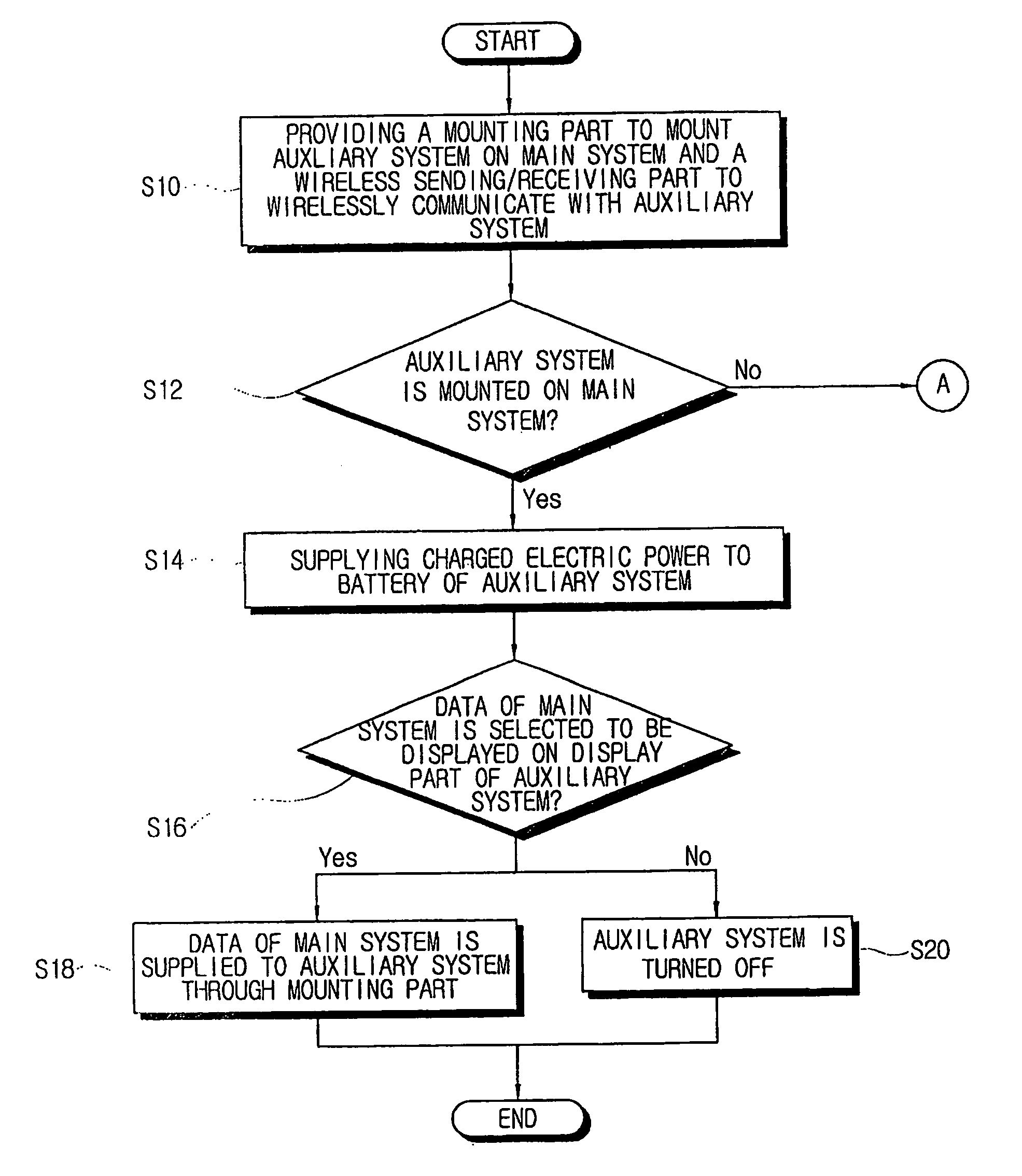
Method of controlling power to an auxiliary system comprising a display part and a wireless sending/receiving part connected to a portable computer through a mounting part
a technology of auxiliary system and control method, which is applied in the direction of portable computer details, electrical apparatus casings/cabinets/drawers, instruments, etc., can solve the problems of inability of users to operate desktop pc when mobility is needed, inconvenient use of notebook computer as pda, and problem of ram capacity of pda, etc., to achieve speedy data processing
- Summary
- Abstract
- Description
- Claims
- Application Information
AI Technical Summary
Benefits of technology
Problems solved by technology
Method used
Image

Examples
Embodiment Construction
[0036]Reference will now be made in detail to the aspects of the present invention, examples of which are illustrated in the accompanying drawings, wherein like reference numerals refer to like elements throughout. The aspects are described below in order to explain the present invention by referring to the figures.
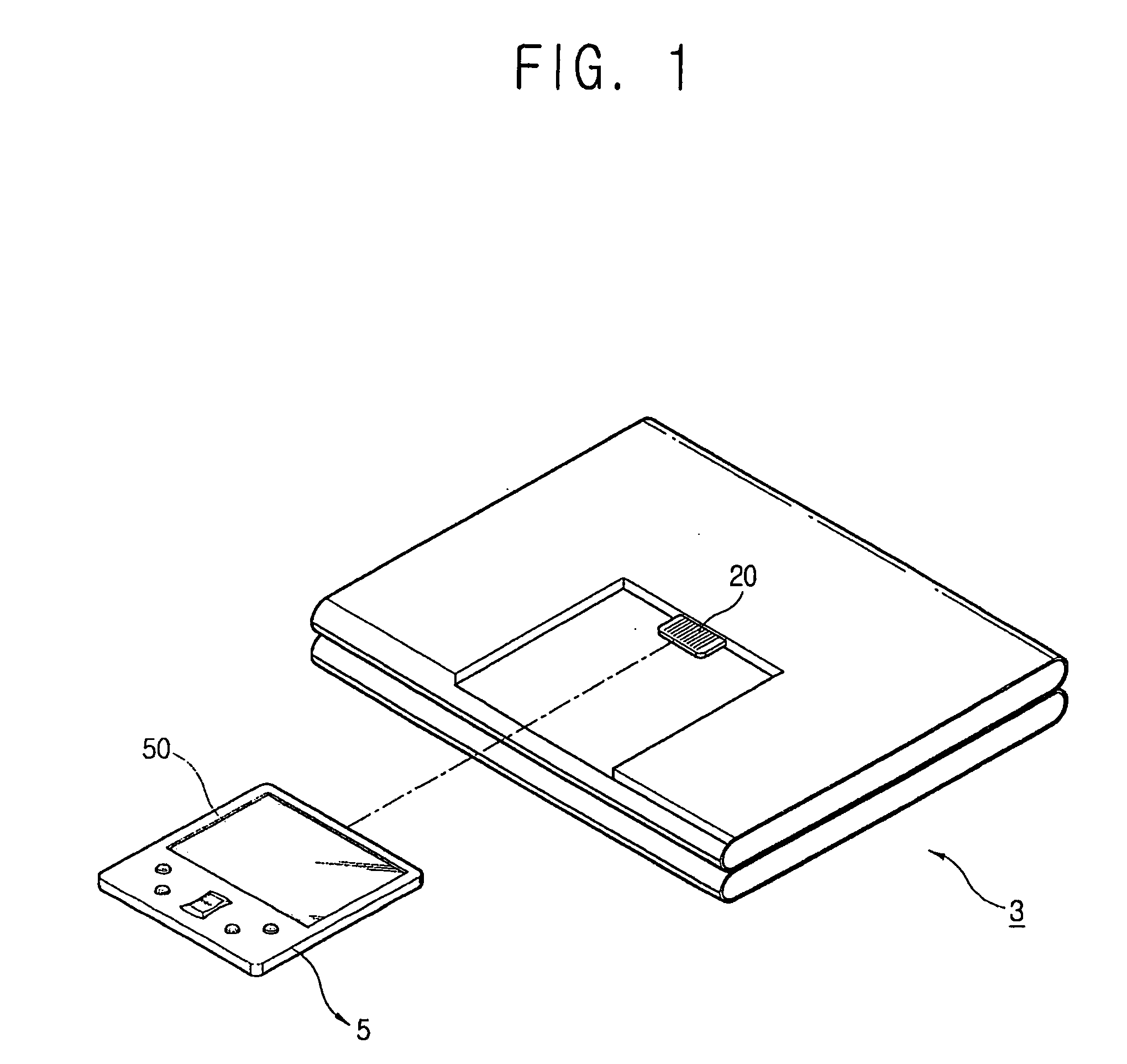
[0037]FIG. 1 is a perspective view of a portable computer system, according to an aspect of the present invention. As shown in FIG. 1, the portable computer is provided on a side of a casing with a mounting part 20 to mount an auxiliary system 5 therein. Thus, the auxiliary system 5 is to be carried with the portable computer.
[0038]Here, the auxiliary system 5 may be an embedded system having an operating system independent of a main system 3 of the portable computer and may include memory, a battery, a display part 50 and the like.
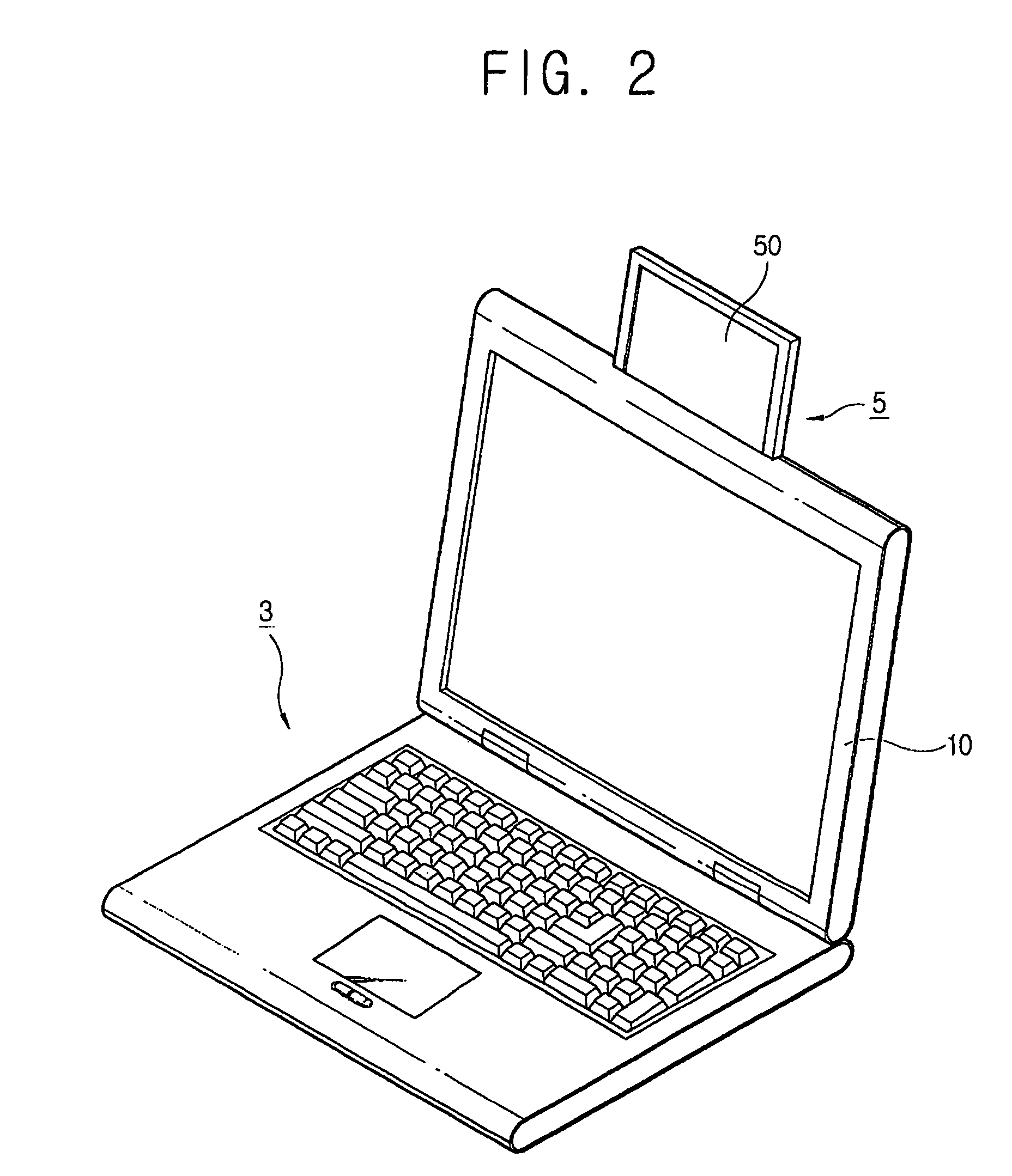
[0039]As shown in FIG. 2, the mounting part 20 may be provided so that the display part 50 of the auxiliary system 5 protrudes from an upper p...
PUM
 Abstract
Description
Claims
Application Information