
Bridge crack detection device and detection method

A detection device, bridge technology, applied in the direction of optical testing flaws/defects, etc., can solve the problems of deviation of dimensional results, difficulty and danger of crack detection, etc.

Active Publication Date: 2017-08-18
TAIYUAN UNIVERSITY OF SCIENCE AND TECHNOLOGY
View PDF15 Cites 24 Cited by
  • Summary
  • Abstract
  • Description
  • Claims
  • Application Information

AI Technical Summary

Problems solved by technology

However, in the actual bridge detection process, due to the complex detection environment of some cross-line bridges and under the bridge, it is more dangerous for the staff to be located under the bridge, making crack detection very difficult. In addition, the hand-held crack observer for irregular bridge cracks is only It can detect the width of a specific area of ​​bridge cracks, resulting in deviations in the size results of bridge crack detection, which affects the evaluation results of judging the safe bearing capacity of bridge structures and evaluating the operation quality of bridges
[0006] Third, machine vision is used to detect bridge cracks, mainly based on digital image processing technology to process the captured cracks, so as to obtain the width, length, area and perimeter of the cracks, but when processing crack images, one is The generally used crack images are crack images captured in a very ideal environment. The captured crack photo is a crack with a very clear edge and almost no burrs; Elimination, these two methods cannot meet the needs of actual projects, the workload is large, the efficiency is low, and the measurement detection is not accurate, and cannot provide an effective basis for objectively evaluating the quality of the pavement and scientifically making maintenance management plans.

Method used


Image

  • Bridge crack detection device and detection method
  • Bridge crack detection device and detection method
  • Bridge crack detection device and detection method

Examples


Embodiment Construction

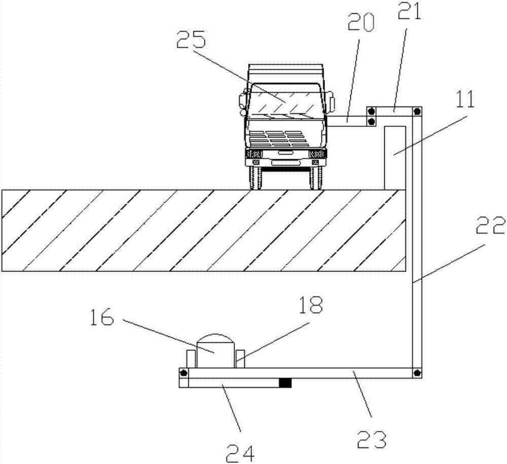
[0080] Such as figure 1 and figure 2 A bridge crack detection device shown includes a control device, an installation trolley 25 moving along the bridge to be detected, a telescopic rod mechanism installed on the installation trolley 25, and a telescopic rod mechanism installed on the telescopic rod mechanism in the bridge to be detected. A detection device for automatic detection of bridge cracks, the telescopic rod mechanism includes a first telescopic rod 20 installed on the installation trolley 25 and arranged horizontally, a second telescopic rod 21 connected to the first telescopic rod 20 and a second telescopic rod 21 connected to the first telescopic rod 25 The third telescopic rod 22 connected with the second telescopic rod 21 and arranged vertically with the second telescopic rod 21, and the fourth telescopic rod 23 connected with the third telescopic rod 22 and arranged vertically with the third telescopic rod 22 and the fourth telescopic rod 23 connected with the ...


PUM


Abstract

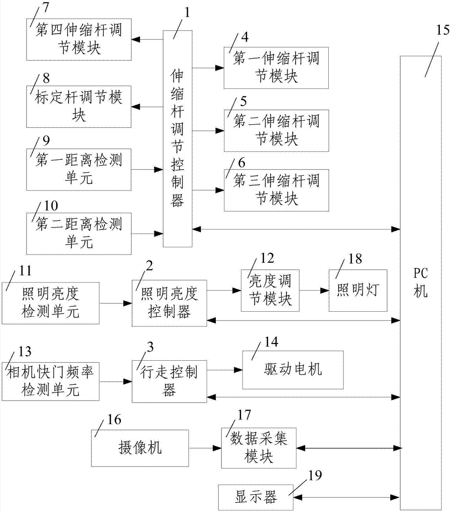
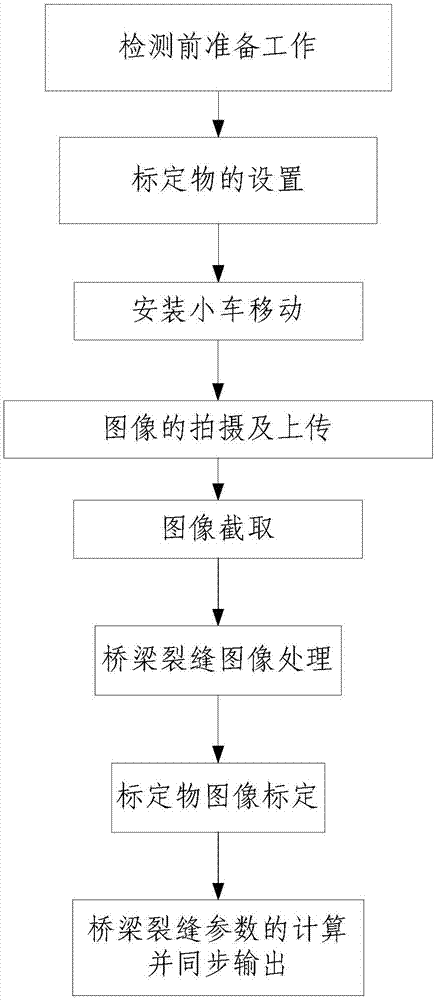
The invention discloses a bridge crack detection device and detection method. The automatic bridge crack detection device comprises a control device, an installation car, a telescopic rod mechanism and a detection device, wherein the control device comprises a data processing device, a display, a walking controller, a camera shutter frequency detection unit, a telescopic rod adjusting device, a telescopic rod adjusting controller, a first distance detection unit, a second distance detection unit, an illuminating brightness detection unit, a brightness adjusting module and an illuminating brightness controller. The detection method comprises the steps of (1) preparatory work before detection; (2) shooting and uploading of an image; (3) image capturing; (4) bridge crack image processing; (5) calibration object image calibration; and (6) calculating and synchronous outputting of bridge crack parameters. The bridge crack detection device is simple in structure, reasonable in design, and convenient to use and operate, accurate and quick detection of the size of bridge cracks can be achieved, and the work efficiency of bridge crack detection and the reliability of detection data are improved.

Description

technical field [0001] The invention belongs to the technical field of bridge crack detection, and in particular relates to a bridge crack detection device and a detection method. Background technique [0002] Nowadays, with the continuous development of bridge technology, not only the total mileage of bridges is also increasing year by year, but also the length of bridges is also lengthening, and bridges are also being built in places with harsh environments. The bridge is the throat of traffic, coupled with the rapid increase of existing traffic volume, the increase of heavy vehicles, and the overspeed and overweight transportation of vehicles, it is difficult for the bearing capacity of the bridge to adapt to the rapid increase of traffic load, and the bridge is in an overloaded state for a long time Cracks are prone to appear in underground work; in addition, the geological conditions, topographical conditions, climatic conditions and the influence of various factors in ...

Claims


Application Information

Patent Timeline
IPC IPC(8): G01N21/95
CPCG01N21/95
Inventor 晋民杰黄智韩智强杨春霞寇文龙王洋
Owner TAIYUAN UNIVERSITY OF SCIENCE AND TECHNOLOGY
Learn More