Knee prosthesis

a knee joint and prosthesis technology, applied in the field of knee joint prosthesis, can solve the problems of increased wear, undesired bending moment in the area of the rotation bearing, and not just, and achieve the effect of clear and simple geometry relationships

Inactive Publication Date: 2007-06-19
WALDEMAR LINK GMBH & CO
View PDF13 Cites 29 Cited by
  • Summary
  • Abstract
  • Description
  • Claims
  • Application Information

AI Technical Summary

Benefits of technology

[0007]The geometric relationships are particularly simple and clear when the radius of curvature of that part of the condylar sliding surfaces cooperating with the tibial sliding surface is substantially constant in the flexion plane, i.e. when the condylar sliding surfaces are configured as arcs of a circle. The invention, however, can also be used when this is no...

Problems solved by technology

The entire load then has to be transmitted on the other side, which leads not just to increased wear, but also to an undesired bending moment in the area of the rotation bearing.
The known prosthesis is therefore not suitable for...

Method used


Image

  • Knee prosthesis
  • Knee prosthesis
  • Knee prosthesis

Examples


Embodiment Construction

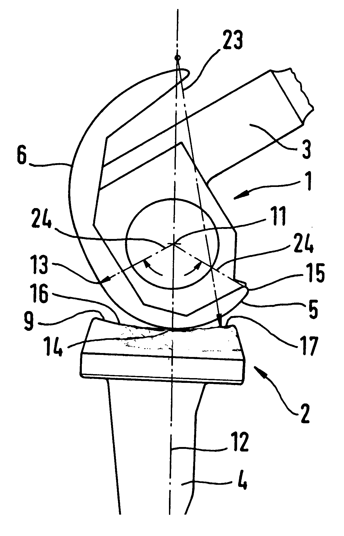
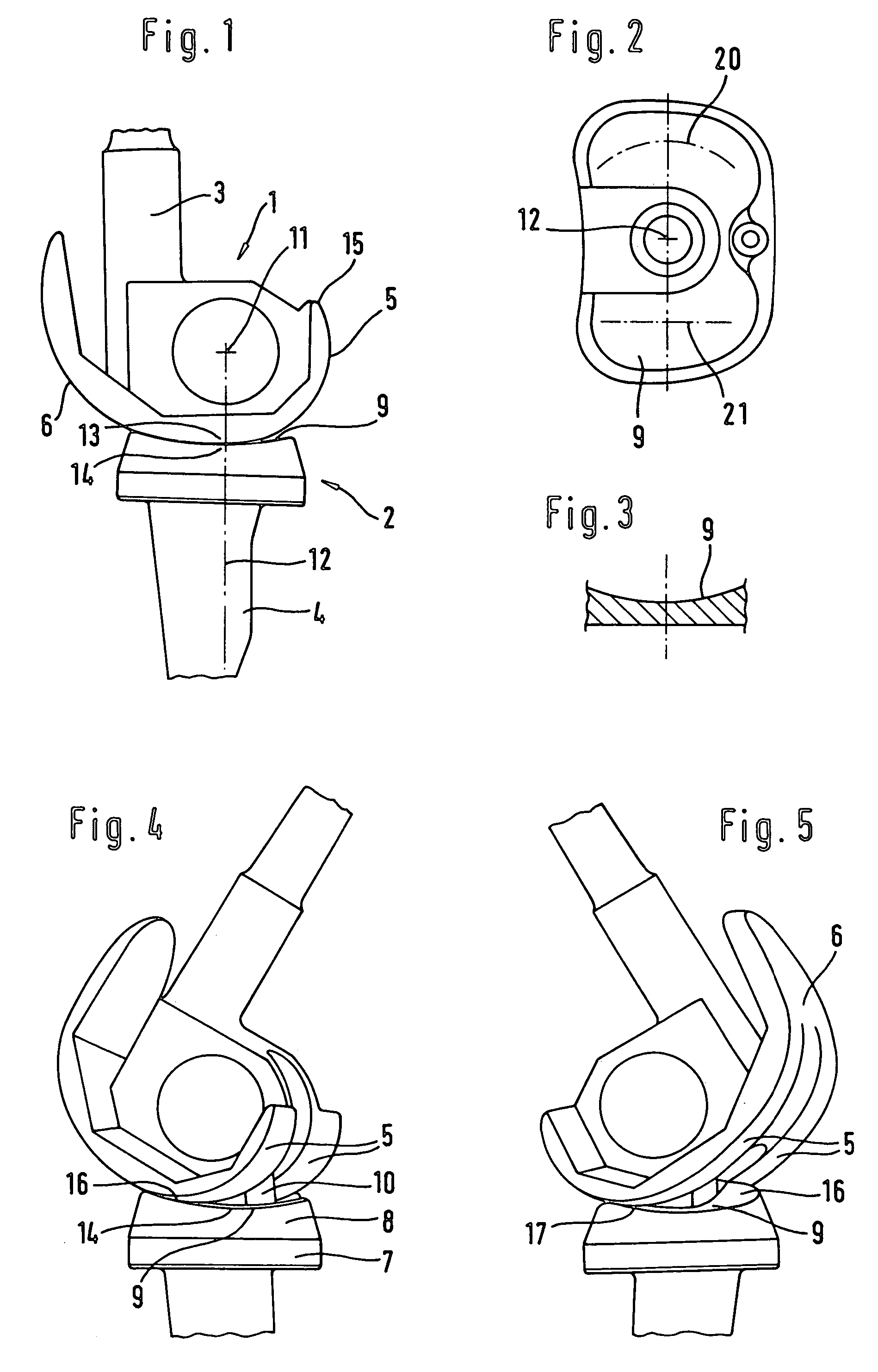
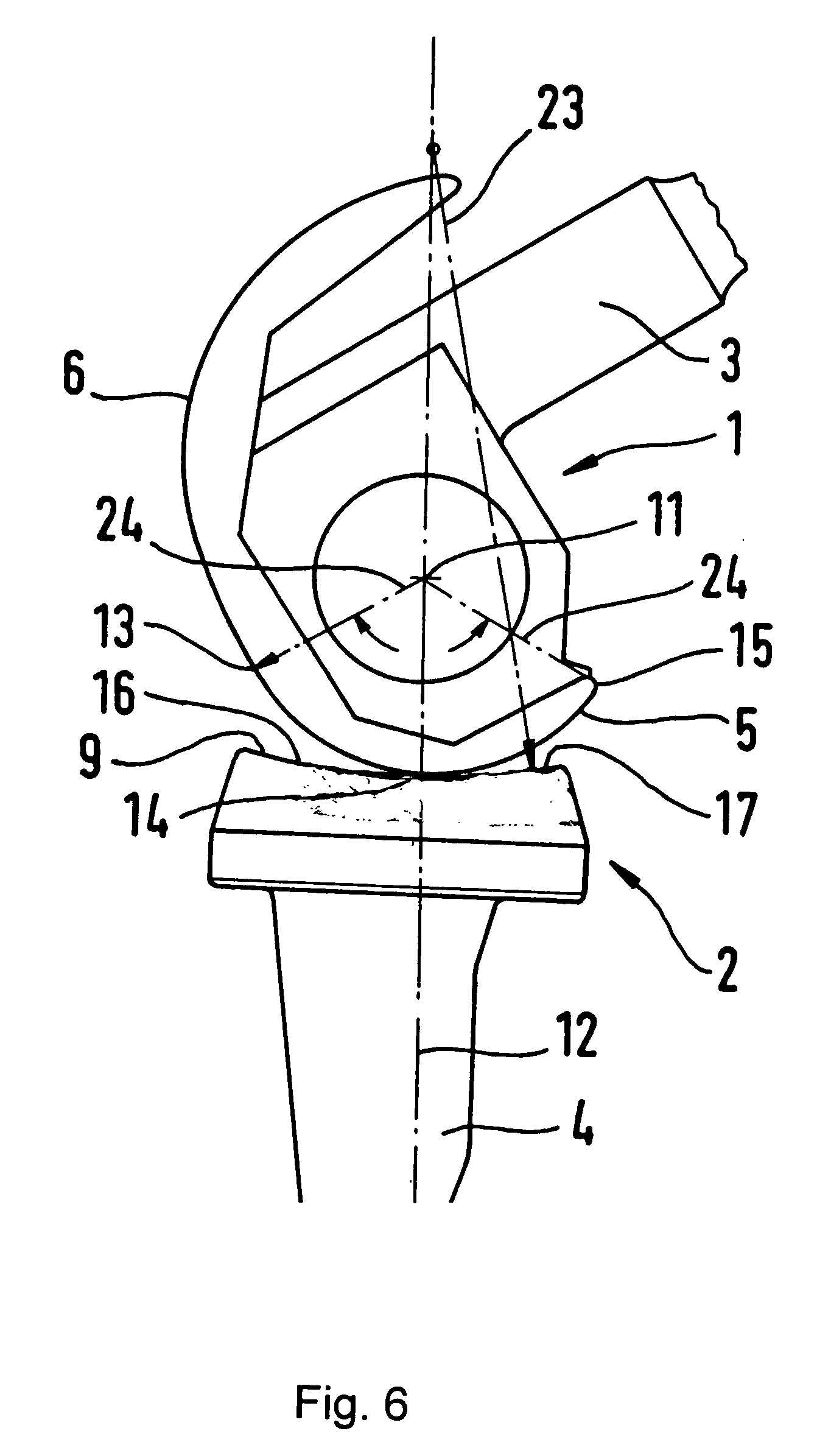
[0014]The prosthesis has a femoral part 1 and a tibial part 2 which, in a known manner, are to be anchored via pins 3, 4 respectively at the lower end of the femur and at the upper end of the tibia. The femoral part 1 has a pair of condylar sliding surfaces 5 which, at the front, come together to form a patellar sliding surface 6. The tibial part 2 forms, at the top, a support plate 7 on which the so-called tibial plateau 8 made of a material promoting sliding, for example polyethylene, is anchored, said tibial plateau 8 forming the tibial sliding surfaces 9 on which the condylar sliding surfaces 5, preferably made of polished metal, slide. The femoral part 1 and the tibial part 2 are coupled to one another by an intermediate part 10 which on the one hand, with the femoral part 1, forms a flexion bearing with axis 11, and, on the other hand, with the tibial part, forms a rotation bearing with axis 12. Details of this construction are explained in European patent applications 1,110,2...


PUM


Abstract

A knee prosthesis includes a femoral prosthetic part which forms a pair of condylar gliding surfaces, a tibial part that has tibial gliding surfaces cooperating with the condylar gliding surfaces and a coupling part that connects the femoral and tibial parts so that they can rotate about a rotational axis that is approximately parallel to the axis of the tibia. If the femoral and tibial parts have the same anteroposterior alignment, an applied load is borne by a central region of the tibial gliding surfaces. The tibial gliding surface slopes upwardly relative to the prosthesis both in front of and behind the central region of the tibial gliding surface so that when the femoral and tibial parts rotate against one another, each of the condylar gliding surfaces remains in contact with its corresponding tibial gliding surface.

Description

BACKGROUND OF THE INVENTION[0001]To replace the human knee joint, prosthesis types are used whose femoral and tibial parts, depending on the state of preservation of the ligament apparatus, are guided relative to one another with a greater or lesser degree of constraint. This concerns the main degrees of freedom of movement of the knee, namely the flexion movement about a transverse axis, the rotation movement about a rotation axis running approximately parallel to the direction of the tibia, and a translation movement in the anteroposterior direction. The least degree of mutual constrained guidance is to be found in what are called uncoupled prostheses, which are made up simply of a pair of femoral condyles and of a tibial sliding surface. They are used in cases where the ligament apparatus is well preserved. The other extreme is constituted by hinge prostheses, which are used in cases of poorly preserved ligament apparatus and which restrict the possible movements of the knee to t...

Claims


Application Information

Patent Timeline
IPC IPC(8): A61F2/38
CPCA61F2/385
Inventor KELLER, ARNOLD
Owner WALDEMAR LINK GMBH & CO
Why Eureka
Try Eureka