Ripple converter

a converter and converter technology, applied in the field of ripple converters, can solve the problems of difficult to predict the characteristics of the capacitor attached to the module, the driving frequency cannot be set to a desired value, and the description is not necessarily accurate, so as to achieve the effect of maintaining stable oscillation

Active Publication Date: 2007-06-19
MURATA MFG CO LTD
View PDF7 Cites 94 Cited by
  • Summary
  • Abstract
  • Description
  • Claims
  • Application Information

AI Technical Summary

Benefits of technology

[0020]A ripple converter according to preferred embodiments of the present invention maintains stable oscillation regardless of the type or capacitance of an output capacitor that is externally attached when the ripple converter is used.

Problems solved by technology

However, the description is not necessarily accurate.
At the stage of designing the module, it is difficult to predict the characteristics of the capacitor attached to the module.
Therefore, in some cases, the driving frequency cannot be set to a desired value when the ripple converter is used.
This problem becomes particularly severe when a ceramic capacitor having a small ESR or ESL is used as the output capacitor.
Therefore, it has been difficult to use a ceramic capacitor as an output capacitor.
As for the response delays of the system, the main cause is a delay caused by the comparator.
That is, the delay decreases as the output voltage changes more rapidly and the delay increases as the output voltage changes more slowly.

Method used


Image

  • Ripple converter
  • Ripple converter
  • Ripple converter

Examples


first preferred embodiment

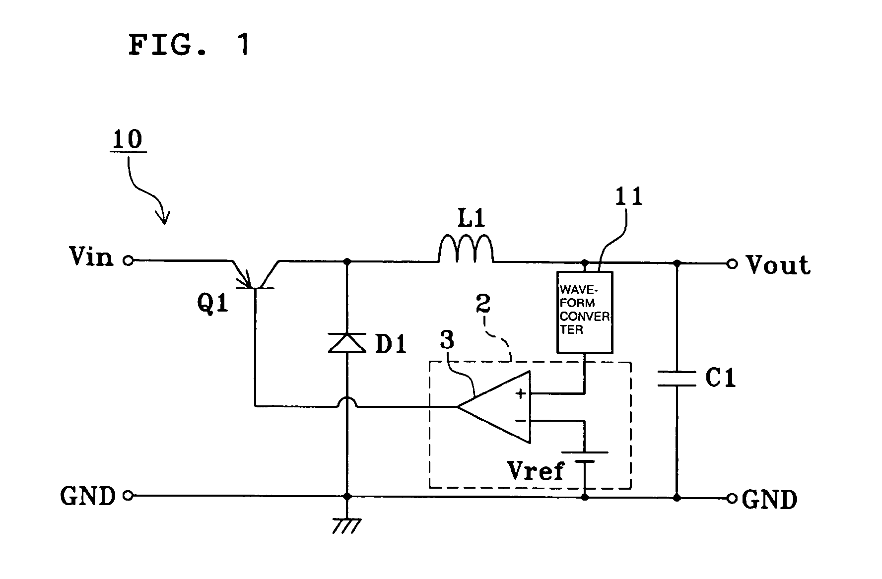
[0038]FIG. 1 shows a circuit diagram of a ripple converter according to a preferred embodiment of the present invention. In FIG. 1, elements corresponding or equivalent to those in FIG. 14B are designated by the same numerals, and descriptions thereof will be omitted.

[0039]In a ripple converter 10 shown in FIG. 1, a waveform converter 11 is disposed on a connecting path between the output terminal Vout and the non-inverting input terminal of the comparator 3. The ripple converter 10 is otherwise the same as the ripple converter 1 according to the related art shown in FIG. 14. In the ripple converter 10, the waveform converter 11 and the comparing unit 2 define a control circuit for exercising feedback control of the ON / OFF of a switching element according to ripple in an output voltage.

[0040]In the ripple converter 10, the waveform of the output voltage vo is converted by the waveform converter 11, and a result of the waveform conversion is compared with the reference voltage vref. ...

second preferred embodiment

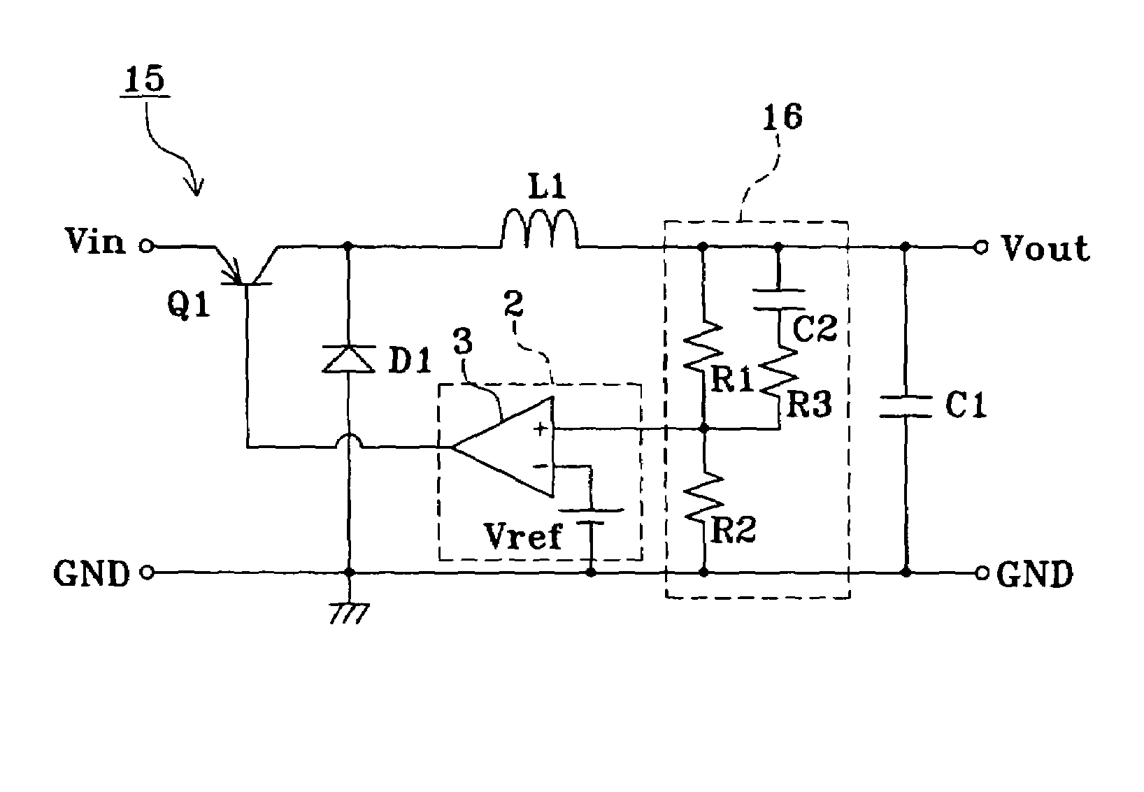
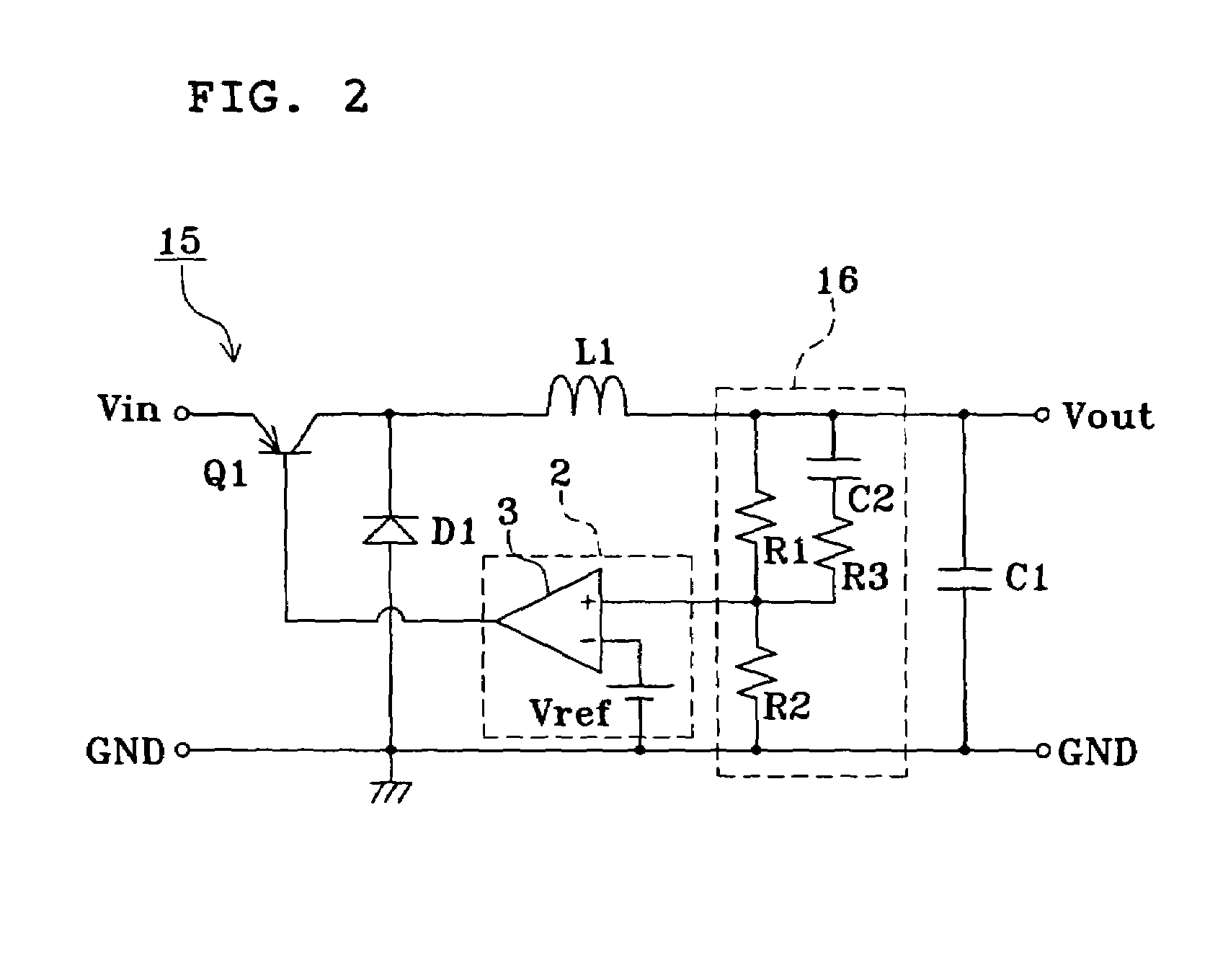
[0041]FIG. 2 shows a circuit diagram of a ripple converter according to another preferred embodiment of the present invention. In FIG. 2, elements corresponding to those in FIG. 1 are designated by the same numerals, and descriptions thereof will be omitted.

[0042]In a ripple converter 15 shown in FIG. 2, the output terminal Vout is connected to the ground via resistors R1 and R2 in series. Furthermore, a capacitor C2 and a resistor R3, connected in series with each other, are connected in parallel to the resistor R1. A node between the resistors R1 and R2 is connected to the non-inverting input terminal of the comparator 3. That is, the resistors R1, R2, and R3, and the capacitor C2 define a waveform converter 16.

[0043]Of the elements of the waveform converter 16, the resistors R1 and R2 provide a circuit for inputting a voltage ver1 that is proportional to the output voltage vo to the non-inverting input terminal of the comparator 3. The capacitor C2 and the resistors R3 and R2 pro...

third preferred embodiment

[0048]FIG. 5 shows a circuit diagram of a ripple converter according to yet another preferred embodiment of the present invention. In FIG. 5, elements corresponding to those in FIG. 2 are designated by the same numerals, and descriptions thereof will be omitted.

[0049]In a ripple converter 18 shown in FIG. 5, instead of the capacitor C2 and the resistor R3 in FIG. 2, a resistor R4 and a capacitor C3, connected in series with each other, are connected in parallel to the resistor R2. Thus, the resistors R1, R2, and R4, and the capacitor C3 define a waveform converter 19.

[0050]Of the elements of the waveform converter 19, the resistors R1 and R2 provide a circuit for inputting a value ver1 that is proportional to the output voltage vo to the non-inverting input terminal of the comparator 3. The resistors R1 and R4 and the capacitor C3 provide a circuit (integrator) for inputting a value ver2 obtained by integrating the output voltage vo to the non-inverting input terminal of the compara...


PUM


Abstract

A ripple converter includes a transistor for switching an input direct-current voltage, a choke coil and a smoothing capacitor for smoothing the switched direct-current voltage, a flywheel diode for causing a current to flow through the choke coil when the transistor is turned off, and a comparing unit for controlling the ON / OFF of the transistor according to ripple in an output voltage. In the ripple converter, a waveform converter is provided on a connecting path between an output terminal and a non-inverting input terminal of a comparator in the comparing unit. A result of converting the waveform of the output voltage is compared with a reference voltage, and a result of the comparison is fed back to the transistor.

Description

BACKGROUND OF THE INVENTION[0001]1. Field of the Invention[0002]The present invention relates to ripple converters. More specifically, the present invention relates to a ripple converter that maintains stable oscillation for switching regardless of the type or capacitance of an externally attached capacitor for smoothing output.[0003]2. Description of the Related Art[0004]A ripple converter generally refers to a DC-DC converter including a switching element for switching an input DC voltage, a choke coil and a smoothing capacitor for smoothing the switched DC voltage, a flywheel diode for causing a current to flow through the choke coil when the switching element is turned off, and a control circuit for controlling the ON / OFF of the switching element according to the magnitude of ripple in an output voltage. Circuits of such a ripple converter are publicly known, as described, for example, in the document, “Transistor Gijutsu Special No. 28, ” Tokushuu, Saishin Dengenkairo Sekkeigij...

Claims


Application Information

Patent Timeline
Patent Type & Authority Patents(United States)
IPC IPC(8): G05F1/565G05F1/56H02M3/155H02M3/156
CPCH02M3/156
Inventor NOMA, TAKASHITAKEMURA, HIROSHI
Owner MURATA MFG CO LTD
Why Eureka
Try Eureka