Vehicle seat

a technology for vehicles and seats, applied in the field of vehicles, can solve the problems of unfavorable transmission of load generated by rearward movement to the headrest holder, inability to reliably move the headrest upward while being tilted forward, and inability to reliably move the headrest while being lowered, so as to achieve smooth and reliable movement.

Inactive Publication Date: 2007-06-26
TOYOTA JIDOSHA KK +1
View PDF12 Cites 28 Cited by
  • Summary
  • Abstract
  • Description
  • Claims
  • Application Information

AI Technical Summary

Benefits of technology

[0009]It is an object of the invention to provide a vehicle seat in which a headrest can be smoothly and reliably moved toward a head of a seated user regardless of an amount of rearward tilting of a seat back, when a vehicle is rear-ended.
[0011]In the vehicle seat according to the first aspect, when the vehicle is rear-ended and the lumbar part of the seated user moves rearward in reaction to the rear-end collision, the operating force generating device generates an operating force when receiving a load generated by the rearward movement, and the operating force transmitting device smoothly moves the headrest frame in accordance with the operation of the operating force generating device. The operating force generating device is provided in an area near a pivot of the seat back, and an amount of positional displacement of the area, which is caused due to the rearward tilting of the seat back, is small. Accordingly, the load generated by the rearward movement of the lumbar part of the seated user is sufficiently transmitted to the operating force generating device regardless of the amount of rearward tilting of the seat back, and therefore a sufficient amount of operating force is reliably generated. As a result, the headrest frame is smoothly and reliably moved along with the headrest support brackets, and the headrest attached to the headrest support brackets is moved toward the head of the seated user smoothly and reliably. The head rest is attached to the headrest support brackets with headrest stays arranged between the headrest and the respective headrest support brackets.
[0016]In the first aspect, the operating force generating device may include a pressure plate which receives the load generated by the rearward movement of the seated user, thereby pressing and moving the driven member. Thus, the load generated by the rearward movement of the seated user can be reliably transmitted to the driven member.
[0018]In the vehicle seat according to the first aspect, when the vehicle is rear-ended and the lumbar part of the seated user moves rearward in reaction to the rear-end collision, the operating force generating device receives the load generated by the rearward movement, thereby generating a sufficient amount of operating force regardless of the amount of rearward tilting of the seat back, and the operating force transmitting device smoothly moves the headrest frame in accordance with the operation of the operating force generating device. As a result, the headrest frame is smoothly and reliably moved along with the headrest support brackets, and the headrest attached to the headrest support brackets is moved toward the head of the seated user smoothly and reliably. The headrest is attached to the headrest support brackets with the headrest stays arranged between the headrest and the respective headrest support brackets. Therefore, according to the invention, when the vehicle is rear-ended, the headrest can be smoothly and reliably moved toward the head of the seated user, regardless of the amount of rearward tilting of the seat back. It is therefore possible to reliably reduce an impact on the neck of the seated user.
[0019]When the operating force transmitting device is formed of the paired pulling cable devices, the both end portions of the headrest frame can be moved smoothly and reliably. Also, flexibility in arrangement of the operating force transmitting device in the seat back is increased, and an increase in the weight of the operating force transmitting device can be minimized.

Problems solved by technology

In the case where the seat back is largely tilted in the rearward direction, the situation may occur in which the load generated by the rearward movement cannot be sufficiently transmitted to the headrest holder and therefore the headrest cannot be reliably moved upward while being tilted forward.
Therefore, the loads received by the right and left headrest holders are likely to be unequal.
As a result, the situation may be caused in which the headrest is tilted in an undesired direction, and cannot be smoothly moved upward while being tilted forward.

Method used


Image

  • Vehicle seat
  • Vehicle seat
  • Vehicle seat

Examples


Embodiment Construction

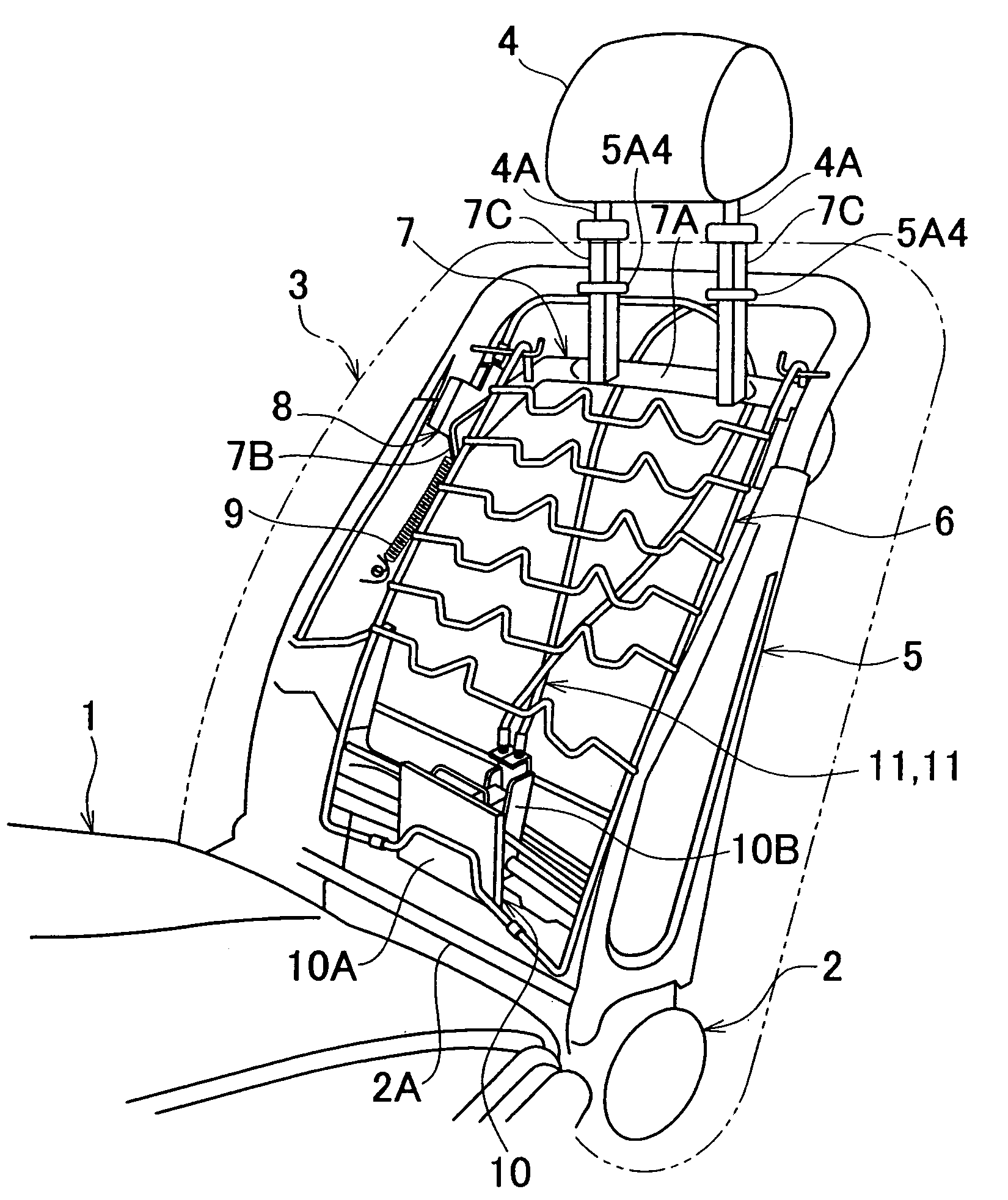
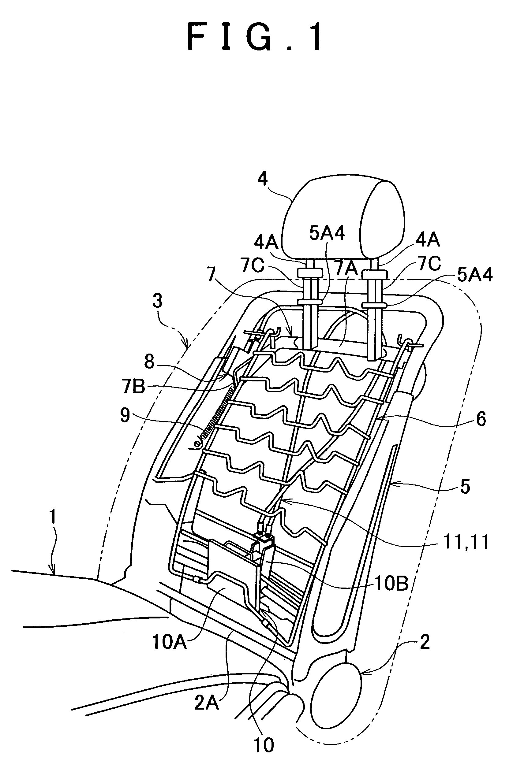
[0038]Hereafter, a vehicle seat according to an embodiment of the invention will be described with reference to accompanying drawings. FIG. 1 is a perspective view showing a structure of a main portion of a vehicle seat according to a first embodiment of the invention.

[0039]As shown in FIG. 1, the vehicle seat according to the first embodiment includes a seat back 3 that is coupled with a rear portion of a seat cushion 1 so as to be tiltable forward / rearward using a tilting mechanism 2. A headrest 4 is detachably attached to an upper portion of the seat back 3 with headrest stays 4A, 4A arranged between the headrest 4 and the seat back 3.

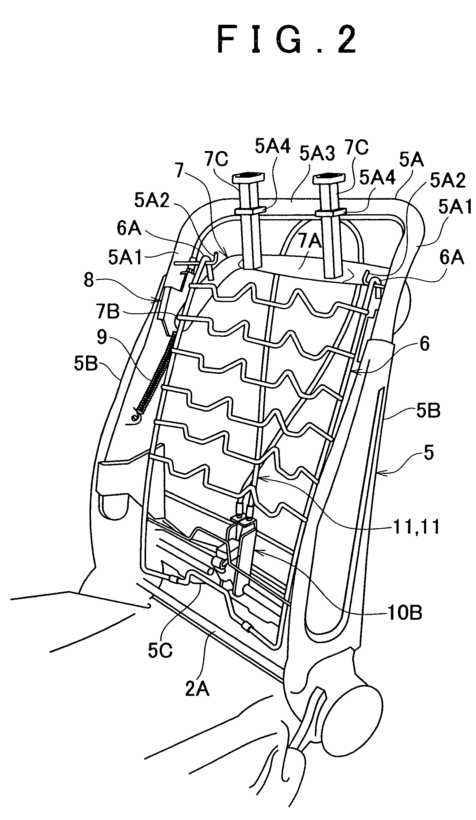
[0040]In the seat back 3, a seat back frame 5, which is a frame of the seat back 3, is embedded in a seat back pad (not shown) formed of a cushion material, for example, urethane foam. As shown in FIGS. 2 and 3, the seat back frame 5 is formed by connecting an upper pipe 5A, right and left side frames 5B, 5B, and a lower frame 5C integrally with eac...


PUM


Abstract

When a vehicle is rear-ended and a seated user moves rearward in reaction to the rear-end collision, a load movement of a lumbar part of the seated user is sufficiently transmitted from a pressure plate of operating force generating means to an operating force generating mechanism, regardless of an amount of rearward tilting of a seat back. Then, a pressure roller serving as a driven member of the operating force generating mechanism largely deflects and sufficiently pulls inner cables of respective pulling cable devices, thereby smoothly moving both end portions of a headrest frame upward. As a result, the headrest frame is moved upward smoothly and reliably, and a headrest is moved in an upward-forward direction, that is, toward the head of the seated user smoothly and reliably.

Description

INCORPORATION BY REFERENCE[0001]The disclosure of Japanese Patent Application No. 2004-184137 filed on Jun. 22, 2004 including the specification, drawings and abstract is incorporated herein by reference in its entirety.BACKGROUND OF THE INVENTION[0002]1. Field of the Invention[0003]The invention relates to a vehicle seat in which a headrest is attached to a seat back.[0004]2. Description of the Related Art[0005]Usually, a headrest is attached to a seat back of a vehicle seat, in order to protect the head of a seated user in the event that the vehicle is rear-ended. The headrest is usually arranged at a position that is slightly apart from the head of the seated user in the rearward direction such that the head of the seated user is prevented from inappropriately contacting the head rest when the vehicle is driven.[0006]Japanese Patent Application Publication No. JP(A) 2001-163099 discloses a known vehicle seat of the above-mentioned type. According to the technology disclosed in Ja...

Claims


Application Information

Patent Timeline
Patent Type & Authority Patents(United States)
IPC IPC(8): B60N2/42B60N2/427B60N2/48B60N2/66
CPCB60N2/42745B60N2/42781B60N2/66B60N2/838B60N2/888B60N2/42
Inventor TAKENAKA, KENICHIOHCHI, MASATOTAMURA, HIROSHIYAMAGUCHI, HIROYOSHIHASEGAWA, MAKOTOITOH, TAKESHI
Owner TOYOTA JIDOSHA KK
Why Eureka
Try Eureka