A helicopter rotary steering engine and a helicopter

A helicopter and rotary technology, applied in the direction of aircraft transmission, aircraft power transmission, aircraft power device, etc., can solve the problems affecting the UAV's flight flexibility and balance, the unreasonable setting of the wire entry position, the gear swing and the Interference and other problems, to achieve the effect of good waterproof and dustproof effect, saving layout space and compact structure

Inactive Publication Date: 2019-04-30
珠海隆华直升机科技有限公司
View PDF14 Cites 6 Cited by
  • Summary
  • Abstract
  • Description
  • Claims
  • Application Information

AI Technical Summary

Problems solved by technology

[0005] Then, when selecting power equipment for UAVs, we need to use steering gears with large loads and torques. However, the traditional large-load and high-torque steering gears have some deficiencies in layout, resulting in a large overall volume. In order to achieve a good The heat dissipation spreads the position of the motor and the rotary potentiometer to increase the space, which makes the shell larger and the overall mass of the steering gear increases, which causes more energy loss during the flight of the UAV, and also affects it to a greater extent. The flexibility and balance of UAV flight are improved; and the setting of the wire entry position of the existing steering gear is not reasonable enough, the shape is single, and the improper position of the wire entry and exit makes it easier for the steering gear to be entangled and pulled during use, resulting in The mechanical function of the steering gear fails during use; the existing reducer adopts single bearing positioning, and the power transmission of the gear is prone to swing and interference, which is not stable enough and reliable, and it also produces a lot of noise, which accelerates the wear of the gear tooth surface , which shortens the life of the gear

Method used


Image

  • A helicopter rotary steering engine and a helicopter
  • A helicopter rotary steering engine and a helicopter
  • A helicopter rotary steering engine and a helicopter

Examples


Embodiment Construction

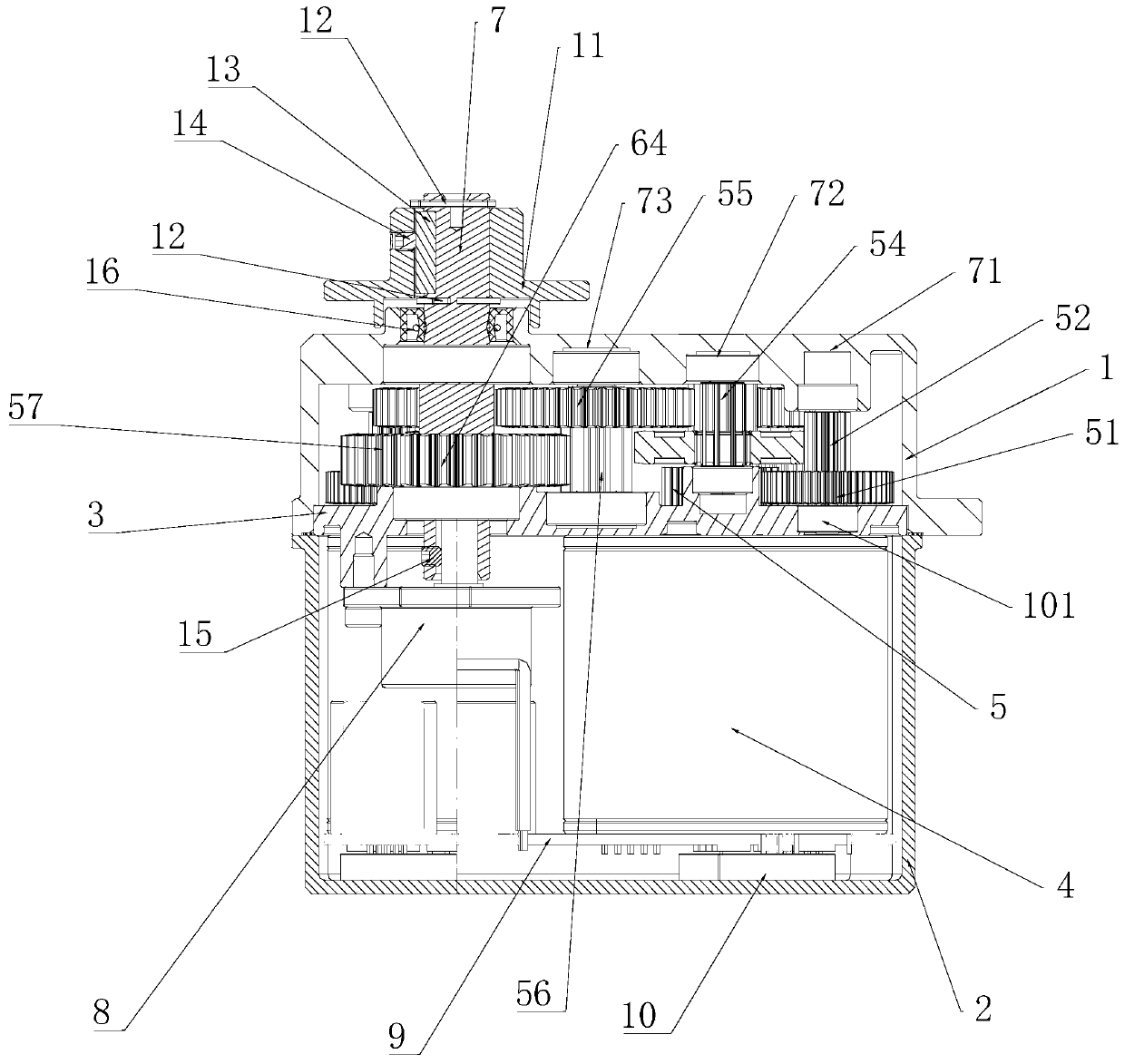
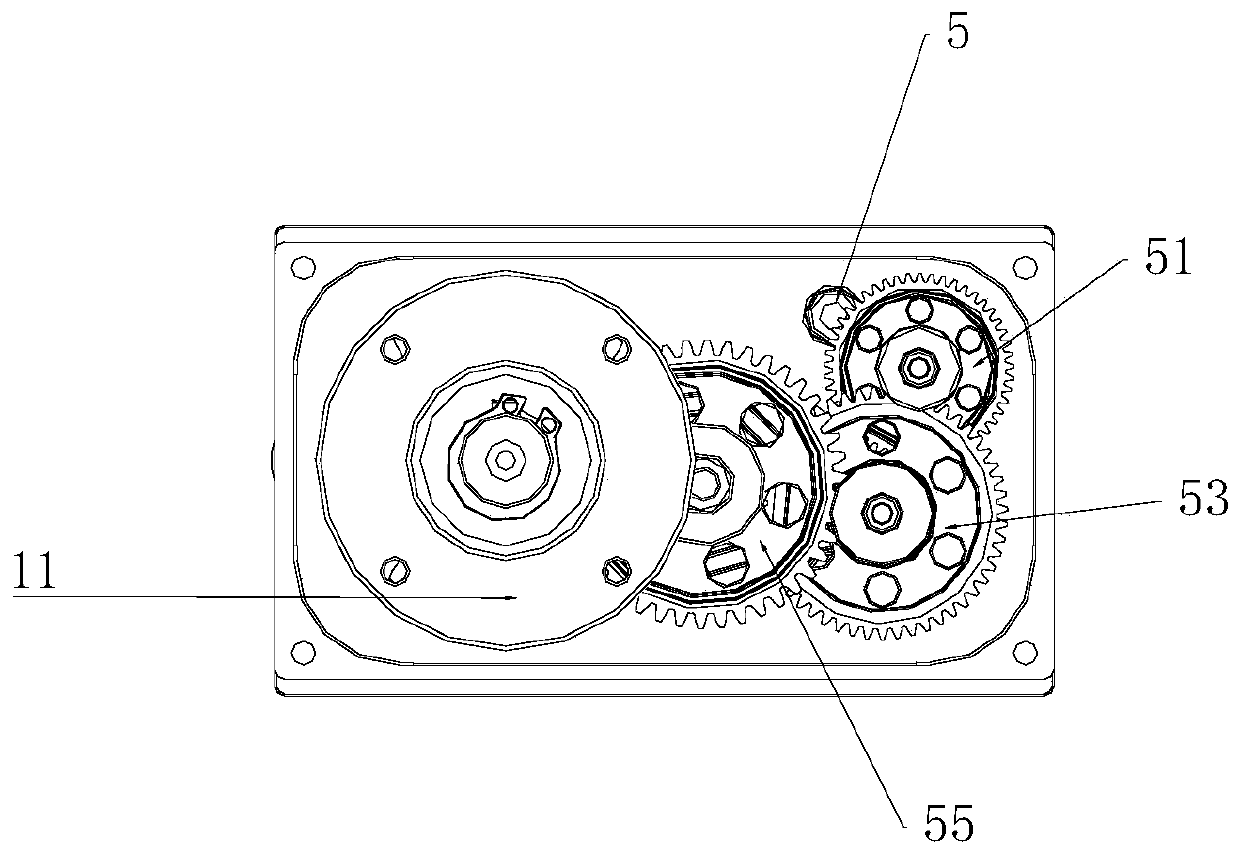
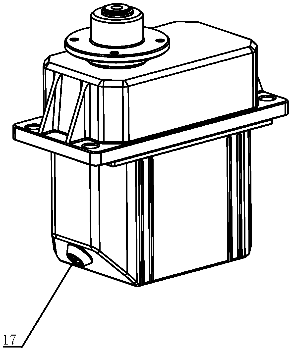
[0024] figure 1 It is a schematic diagram of the internal structure of the present invention, figure 2 It is a schematic diagram of the arrangement of the gear set of the present invention, image 3 It is a schematic diagram of the structure of the present invention, Figure 4It is a structural schematic diagram of the motor sealing plug of the present invention, as shown in the figure: it includes a power source 4, an output shaft 7 arranged parallel to the power source, and a deceleration output assembly arranged between the output end of the power source and the output shaft 7; the deceleration output The assembly includes an input gear 5 fixed at the output end of the power source, an output gear 57 fixed on the output shaft, and a transmission gear assembly drivingly connected between the input gear 5 and the output gear 57 . In this embodiment, the power source 4 is generally a motor, and the transmission gear assembly includes a first-stage input gear 51 and a first-...


PUM


Abstract

The invention discloses a helicopter rotary steering engine and a helicopter. The helicopter rotary steering engine comprises a power source and a speed reduction output assembly. The helicopter rotary steering engine and the helicopter are compact in structure, small in size and convenient to mount and dismount; a circuit board is fixed at the bottom of the steering engine lower shell through a silica gel block that plays a role in buffering and protecting the circuit board, so that circuit pins are protected from being damaged, and heat dissipation of the circuit board is facilitated; the shell is made of an aluminum alloy material and light in weight, high in strength and rapid in heat dissipation; each group of gears are positioned by adopting double bearings, so that the whole movement is more stable and reliable, the noise is low, tooth surface meshing is increased, tooth surface abrasion is reduced, and the service life of the gear groups are prolonged; a motor and a potentiometer are arranged in parallel, so that the space is effectively shortened, the size of the shell is reduced, and the weight of the shell is reduced; and each pair of rolling bearings is directly embedded in the shell structure, the integrated design improves the strength, and the arrangement space is saved.

Description

technical field [0001] The invention relates to the technical field of drivers, in particular to a helicopter rotary steering gear and a helicopter. Background technique [0002] The steering gear is mainly composed of a casing, a circuit board, a coreless motor, gears and a position detector. Its working principle is that the receiver sends a signal to the steering gear, and the IC on the circuit board judges the direction of rotation, and then drives the coreless motor to start rotating, and the power is transmitted to the swing arm through the reduction gear, and the signal is sent back by the position detector , to determine whether the location has been reached. The position detector is actually a variable resistor. When the steering gear rotates, the resistance value will change accordingly. By detecting the resistance value, the rotation angle can be known. In a general servo motor, a thin copper wire is wound on a three-pole rotor. When current flows through the co...

Claims


Application Information

Patent Timeline
Patent Type & Authority Applications(China)
IPC IPC(8): B64C13/50
CPCB64C13/50
Inventor 刘文献陶志浩张伟陈劲舟齐亚东谢泽峰高洪军
Owner 珠海隆华直升机科技有限公司
Why Eureka
Try Eureka