Eureka AIR delivers breakthrough ideas for toughest innovation challenges, trusted by R&D personnel around the world.

Reflection ring lifting device for improving thermal field of zone-melting single-crystal furnace

A technology of reflective ring and furnace thermal field, which is applied in the direction of single crystal growth, self-regional melting method, crystal growth, etc., can solve the problems of low quality of grown single crystal and unadjustable thermal field, and achieve optimized thermal field distribution, convenient Front and rear position adjustment, effect of crack prevention

Active Publication Date: 2012-07-04
ZHEJIANG JINGSHENG MECHANICAL & ELECTRICAL
View PDF5 Cites 6 Cited by
  • Summary
  • Abstract
  • Description
  • Claims
  • Application Information

AI Technical Summary

Problems solved by technology

In traditional zone melting furnace equipment, there is generally no reflective ring device or the reflective ring is in a fixed installation form, and the thermal field under the melting zone cannot be adjusted, which makes the quality of grown single crystals not high, which cannot meet the current requirements for high-quality single crystals

Method used


Image

  • Reflection ring lifting device for improving thermal field of zone-melting single-crystal furnace
  • Reflection ring lifting device for improving thermal field of zone-melting single-crystal furnace
  • Reflection ring lifting device for improving thermal field of zone-melting single-crystal furnace

Examples

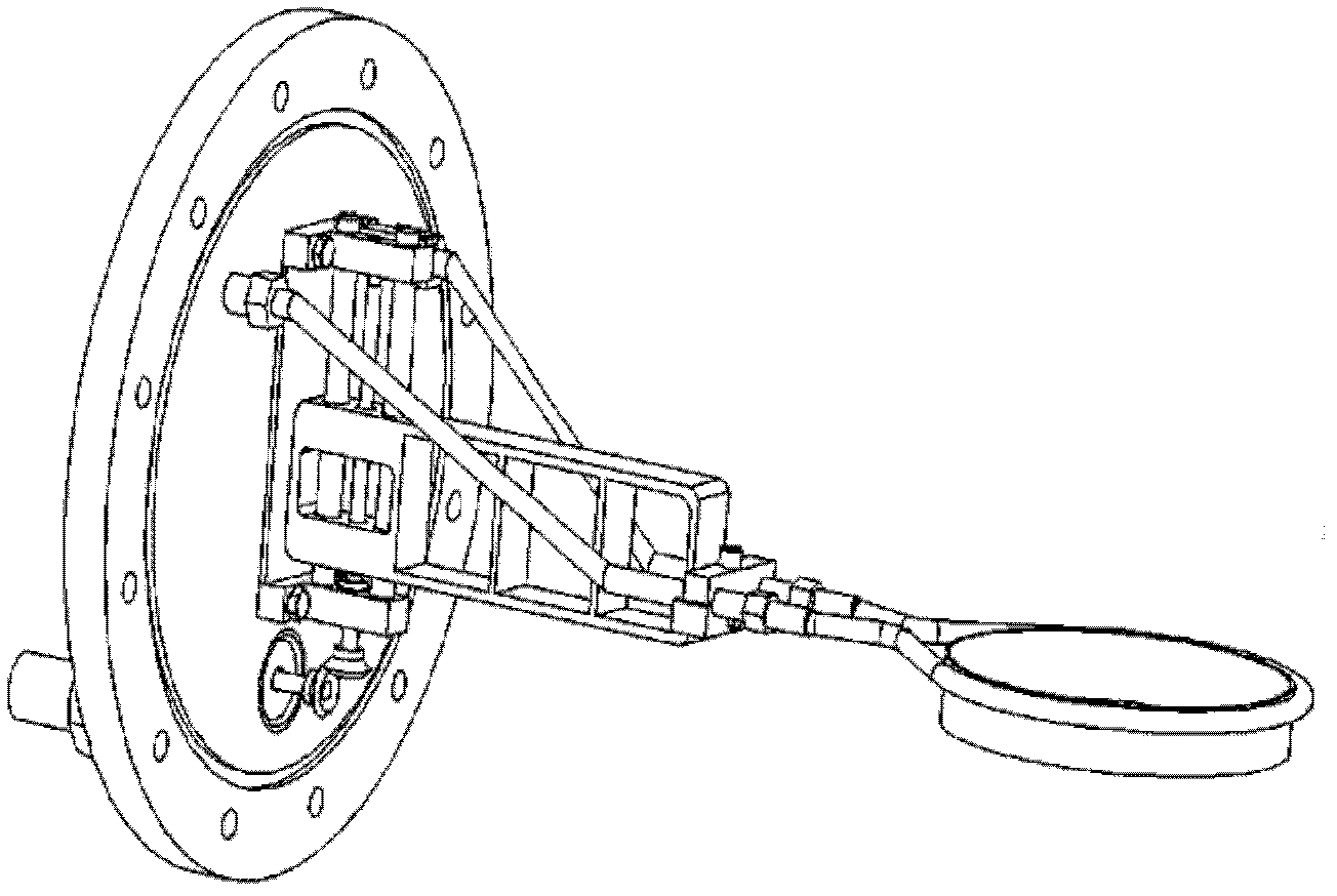
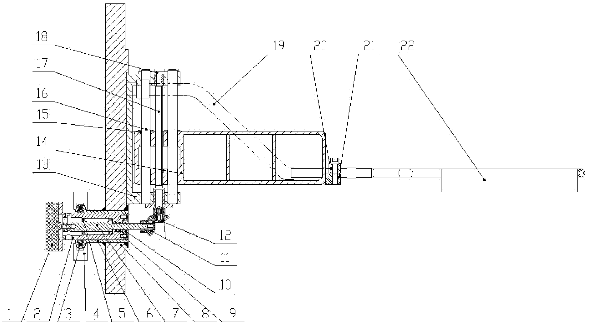
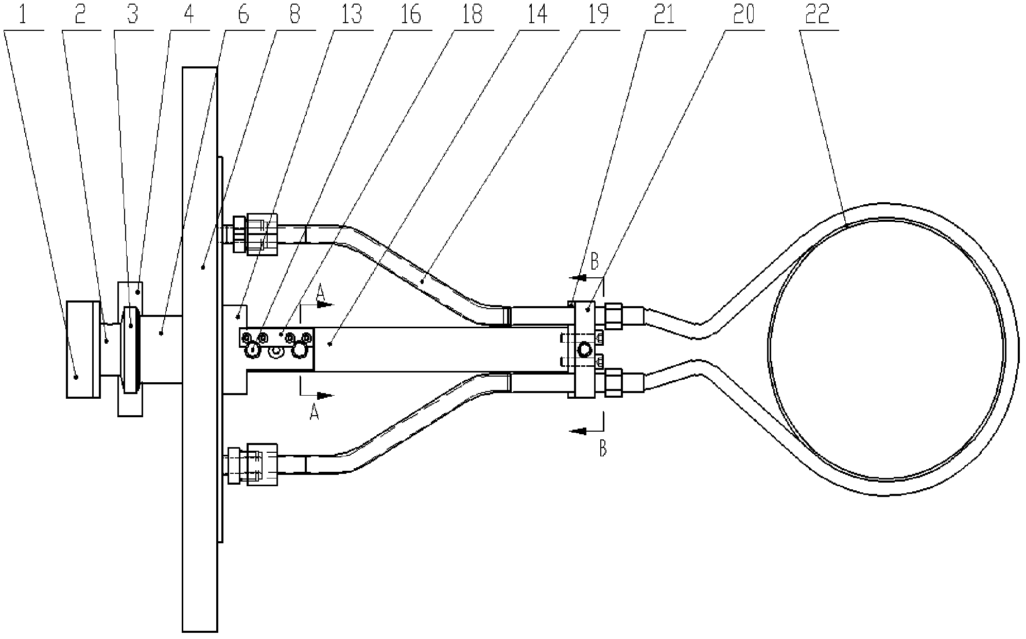

Embodiment Construction

[0026] Specific embodiments of the present invention will be described below in conjunction with the accompanying drawings.

[0027] Such as figure 2 , 3 shown. The hoisting device for the reflective ring of the zone melting single crystal furnace includes a reflective ring 22 and a window flange 8 fixed on the flange of the main furnace chamber. The reflective ring 22 is an annular red copper sheet with a diameter of 200-350 mm and a thickness of 3-10 mm. A hollow cooling pipe is set on the outer side of the reflection ring 22, and the two ends of the cooling pipe are respectively connected to the metal sealing joint provided on the inner wall of the window flange 8 through the bellows 19; the metal sealing joint is arranged through the window flange 8, And stretch out the outer wall of the window flange 8 as the inlet and outlet of cooling water; the part where the bellows 19 is connected with the cooling pipe is fixed on one end of the bracket 14; the other end of the br...


PUM


Abstract

The invention relates to manufacturing equipment for non-mental crystals and aims at providing a reflection ring lifting device for improving the thermal field of a zone-melting single-crystal furnace. The reflection ring lifting device comprises a reflection ring and a window flange of a main furnace chamber; an outer side ring of the reflection ring is provided with a hollow cooling pipe; the two ends of the cooling pipe are connected to metal sealing joints on the window flange; the metal sealing joints are extended out of the outer wall of the window flange to be used as a cooling water inlet and outlet; the cooling pipe is fixed at one end of a support which is positioned on a vertical optical shaft; an engaged vertical lifting lead screw is also arranged on the support; and a transmission shaft is connected with the lifting lead screw through a bevel gear pair. The reflection ring lifting device has the advantages of realizing the lifting movement of the reflection ring in a hearth of the zone-melting furnace, being smooth and reliable in movement, being capable of realizing front and back adjustment, being convenient for aligning the reflection ring and a heating coil and being capable of forming a favorable thermal field in a melting zone, thereby increasing the quality of single crystals. By adjusting the position of the reflection ring, the reflection ring has thermal insulation effect on the single crystals, reduces the thermal stress inside the crystals and prevents detects such as flaws and the like from occurring in the single crystals due to undercooling.

Description

technical field [0001] The invention relates to non-metallic crystal manufacturing equipment, in particular to a reflection ring lifting device for improving the thermal field of a zone melting single crystal furnace. Background technique [0002] Silicon material is the foundation of modern information society. It is not only the main functional material of photovoltaic power generation and other industries, but also the basic material of semiconductor industry, especially power electronic devices. The production of single crystal silicon by zone melting method (FZ) is a new type of single crystal growth method different from Czochralski furnace (CZ). It uses high-frequency induction heating coils to partially melt high-purity polycrystalline materials. The melting zone relies on The surface tension of the molten silicon and the magnetic buoyancy provided by the heating coil are in a suspended state, and then the molten silicon is pulled into a single crystal from the botto...

Claims


Application Information

Patent Timeline
IPC IPC(8): C30B13/20C30B13/32
Inventor 欧阳鹏根石刚傅林坚曹建伟陈明杰王丹涛邱敏秀蒋庆良
Owner ZHEJIANG JINGSHENG MECHANICAL & ELECTRICAL
Why Eureka
Eureka Blog
Learn More