Linear vibration device for electrolytic machining

A linear vibration and vibration shaft technology, applied in electric machining equipment, electrochemical machining equipment, attachments, etc., can solve the problems of poor buffer damping, complex structure, etc., to reduce frictional resistance, stable and reliable transmission, and meet vibration requirements. desired effect

Active Publication Date: 2018-09-07
CHANGZHOU INST OF TECH
View PDF5 Cites 6 Cited by
  • Summary
  • Abstract
  • Description
  • Claims
  • Application Information

AI Technical Summary

Problems solved by technology

[0005] The purpose of the present invention is to overcome the shortcomings of the existing linear vibration mechanism such as complicated structure and poor buffering and damping effect, and provide a linear vibration device for electrolytic machining. By adopting the technical solution of the present invention, the input shaft and the vibration shaft are cleverly used to utilize the piston cylinder The structure is connected, and the cam structure is used to realize the change of the hydraulic oil space in the piston cylinder to realize the reciprocating linear vibration motion of the vibration shaft up and down, and convert the rotational motion of the drive motor into linear reciprocating vibration. The vibration amplitude can be controlled by the cam track, with hydraulic transmission Cushioning and damping effect, without complex hydraulic control system, simple and compact structure design, flexible and convenient to use, which greatly meets the linear vibration needs of electrolytic machining

Method used


Image

  • Linear vibration device for electrolytic machining
  • Linear vibration device for electrolytic machining
  • Linear vibration device for electrolytic machining

Examples


Embodiment

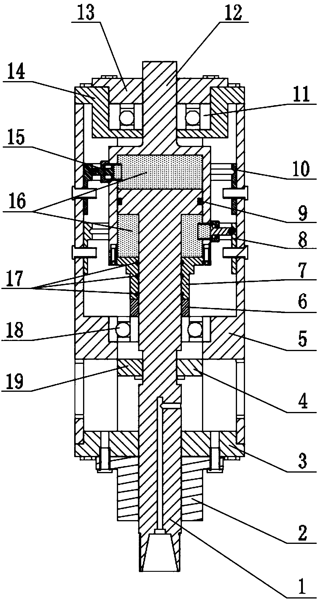
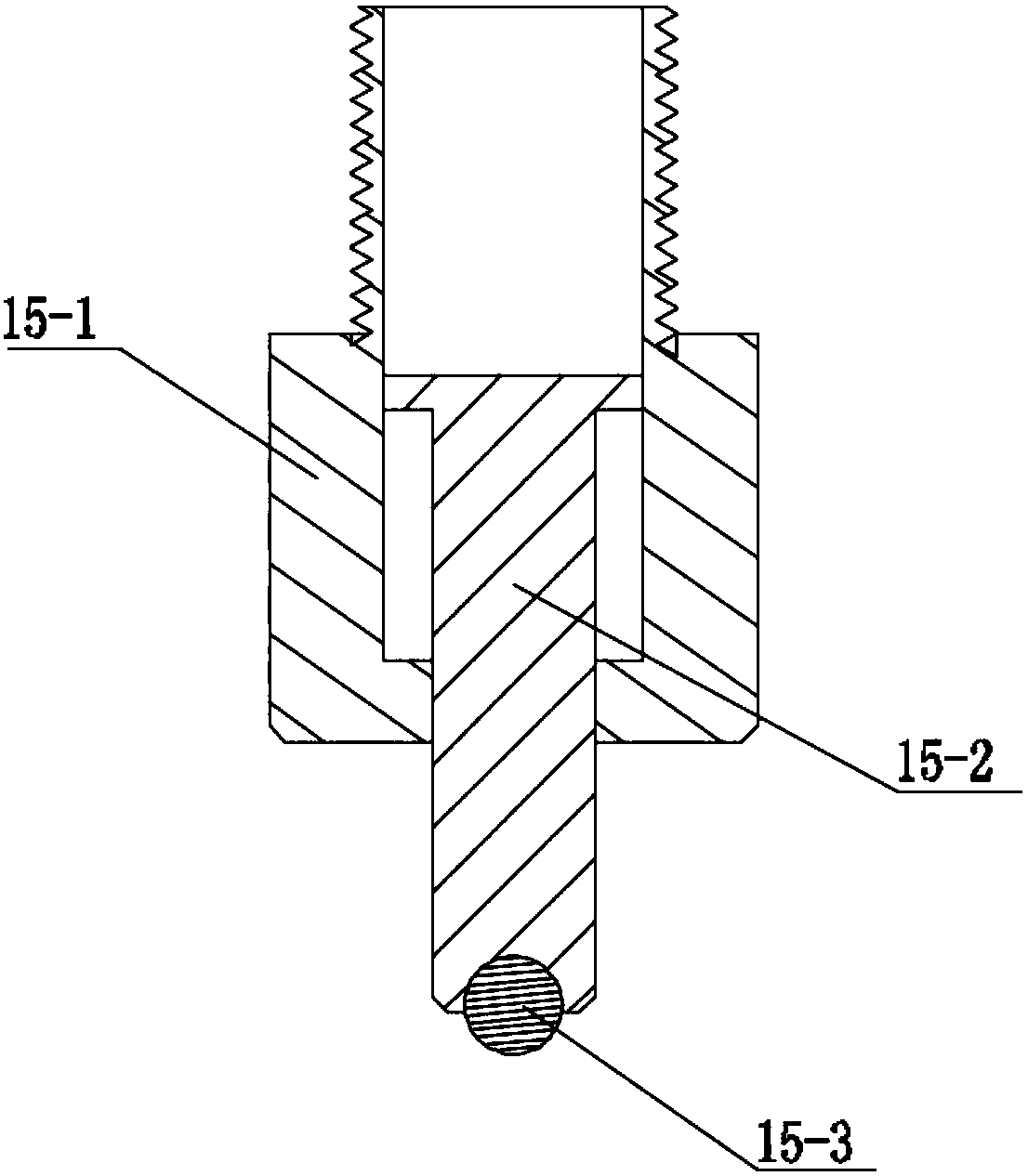
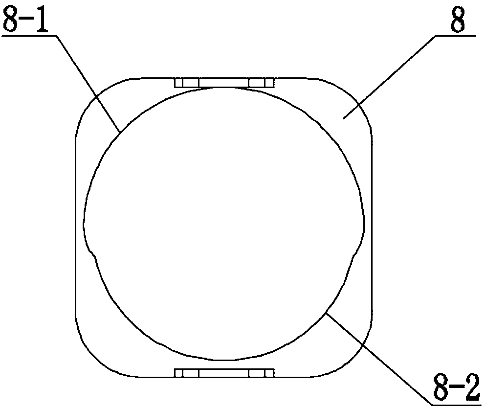
[0035] combinefigure 1 and figure 2 As shown, a linear vibrating device for electrolytic machining in this embodiment includes a box body 5, an input shaft 12, a vibrating shaft 1, a lower cam 8, an upper cam 10 and a small oil cylinder 15, and the box body 5 is used as the main body of the linear vibrating device The input shaft 12 can be connected with an external motor and rotated under the drive of the external motor. The input shaft 12 is rotated and installed in the box body 5, and the vibration shaft 1 and the input shaft 12 are installed coaxially. In the box body 5, and between the vibration shaft 1 and the box body 5 is also provided with a stop structure, one end of the input shaft 12 has a piston cylinder, the piston cylinder can be integrally formed at one end of the input shaft 12, the vibration shaft 1 One end has a piston matched with the above-mentioned piston cylinder, the piston can slide up and down in the piston cylinder, and the piston is also provided w...


PUM


Abstract

The invention discloses a linear vibration device for electrolytic machining ad belongs to the field of vibration mechanisms. One end of an input shaft of the linear vibration device is provided witha piston cylinder, one end of a vibration shaft is provided with a piston matched with the piston cylinder, the cylinder body side wall of the piston cylinder is provided with two sets of small oil cylinders, and the cam outline of an upper cam and the cam outline of a lower cam prop against small oil cylinder piston rods of the corresponding small oil cylinder correspondingly. The input shaft andthe vibration shaft are connected ingeniously through the piston cylinder structure; and meanwhile, through the cam structures, the space change of hydraulic oil in the piston cylinder is realized, vertically reciprocating linear vibration movement of the vibration shaft is realized, the rotating movement of a drive motor is converted to linear reciprocating movement, the vibration amplitude canbe controlled by cam tracks, the buffering and damping effect of hydraulic transmission is achieved, and no complex hydraulic control system is needed. The linear vibration device is simple and compact in structural design and flexible and convenient to use and greatly meets the linear vibration requirement of electrolytic machining.

Description

technical field [0001] The invention relates to a linear vibrating mechanism, more specifically, to a linear vibrating device for electrolytic machining. Background technique [0002] In the technical field of machining, a linear reciprocating mechanism is often required. For example, in electrolytic machining, the spindle of the electrolytic machining machine usually needs to drive the cathode tool to move up and down to perform electrolytic machining. There are many types of existing linear motion mechanisms, such as linear motors, cylinders, oil cylinders, and rack-and-pinion mechanisms, crank-slider mechanisms, or screw-nut mechanisms to convert the rotational motion of the motor into linear motion. Compared with cylinders and oil cylinders, linear motors have lower dynamic rigidity and cannot play the role of buffering and damping. Air cylinders and oil cylinders need to be equipped with air pressure and oil pressure systems, resulting in complex equipment structures....

Claims


Application Information

Patent Timeline
Patent Type & Authority Applications(China)
IPC IPC(8): B23H3/00B23H11/00
Inventor 干为民安静金祥曙王祥志黄亮徐波
Owner CHANGZHOU INST OF TECH
Why Eureka
Try Eureka