Prosthesis liner or socket with a seal at the distal end

a technology of prosthesis and seal, applied in the field of prosthesis liner or socket with seal at the distal end, can solve the problems of partial vacuum collapse, prosthetic socket cannot be retained on the liner,

Active Publication Date: 2007-06-26
KAUPTHING BANK
View PDF72 Cites 96 Cited by
  • Summary
  • Abstract
  • Description
  • Claims
  • Application Information

AI Technical Summary

Benefits of technology

[0012]As compared to the above discussed state of the art, the objective of the present invention is to create a prosthetic socket assuring reliable retention by partial vacuum even when the prosthetic socket has openings at its distal end.

Problems solved by technology

If so, the partial vacuum then collapses and the prosthetic socket can hardly be retained on the liner.

Method used


Image

  • Prosthesis liner or socket with a seal at the distal end
  • Prosthesis liner or socket with a seal at the distal end
  • Prosthesis liner or socket with a seal at the distal end

Examples


Embodiment Construction

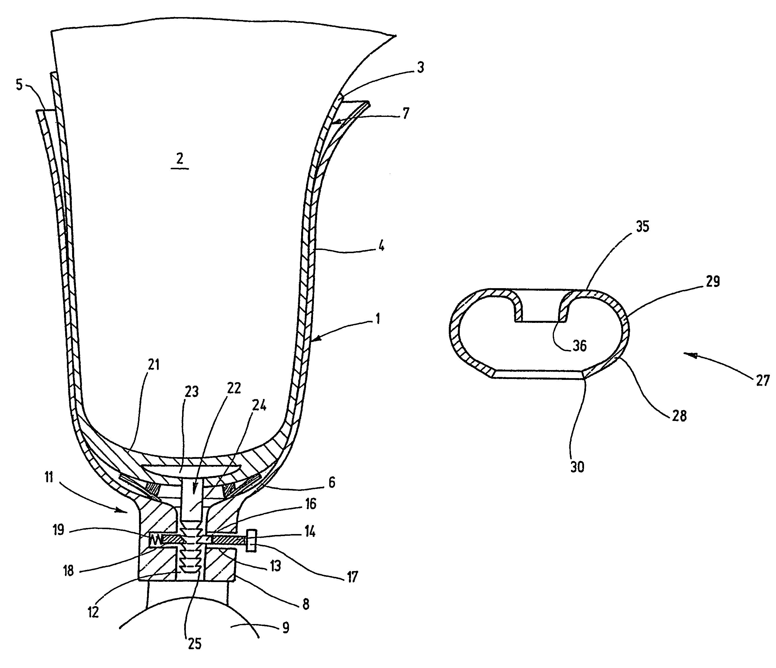
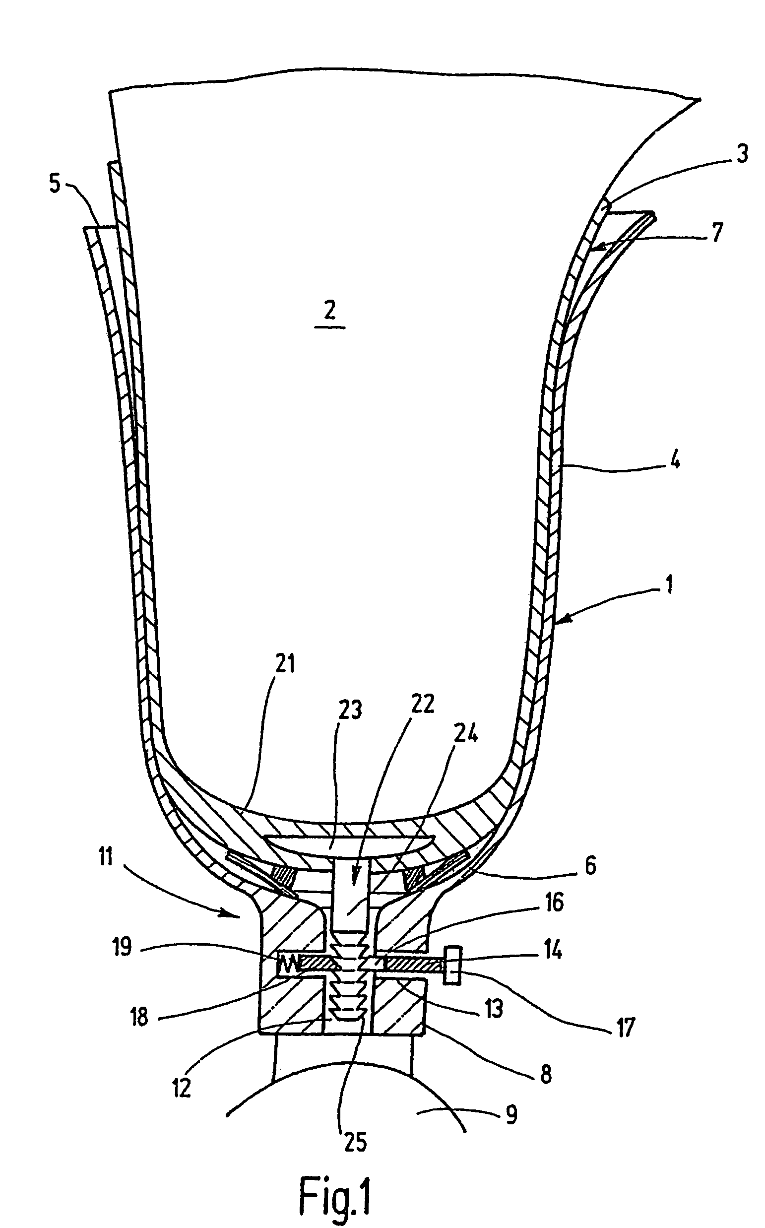
[0031]In highly schematic form, and as an example of the present invention, FIG. 1 shows a prosthetic socket 1 for use above-the-knee, into which an amputation residual limb 2 onto which a liner 3 was donned has been received.

[0032]The prosthetic socket 1 has a cup-shape configuration comprising a lateral wall 4 subtending an opening 5 at its proximal end and being closed by an inverted dome-like base 6 at its distal end. The wall 4 and the base 6 merge integrally into each other and define a corresponding inner volume 7 that receives the amputation residual limb 2.

[0033]At its lower end, the base 6 is integrally extended by a cylindrical fitting 8 connected to an artificial knee 9.

[0034]A two-part lock 11 assures reliable and mechanical retention of the liner 3 in the prosthetic socket 1. The lock 11 is fitted with a cylindrical borehole 12 which is located in the cylindrical extension 8 and which at its upper end and through a conically widening opens into the inner volume 7 of th...


PUM


Abstract

A prosthetic liner for receiving a residual limb has a body with an open proximal end and a closed distal end. The liner includes a seal having an annular sealing lip positioned about the body axis on the body distal end. The sealing lip includes a root that is secured to the body distal end, and a sealing edge that extends from the root so as to form an opening and is biased away from the body distal end.

Description

BACKGROUND[0001]A. Field of the Invention[0002]This invention relates to prosthesis liner or socket having a seal at its distal end.[0003]B. Related Art[0004]With prostheses in general and leg prostheses in particular, a substantial effort is made to spread the retention force with which the prosthesis is attached to the involved residual limb over as large a surface as possible. So-called suction prostheses are especially advantageous in that respect, as they are sealed hermetically against the residual limb. When a force occurs tending to pull the prosthesis off the residual limb, a partial vacuum is produced which, in cooperation with the external atmospheric pressure, retains the prosthesis on the residual limb.[0005]The suction socket presumes a positive air tight seal. When leaks arise, the partial vacuum at once disappears and the residual limb slips out of the socket.[0006]It is clear on its face that such an event occuring with a leg prosthesis entails a dangerous fall. If ...

Claims


Application Information

Patent Timeline
Patent Type & Authority Patents(United States)
IPC IPC(8): A61F2/78A61F2/00A61F2/50A61F2/80
CPCA61F2/7812A61F2/80A61F2002/30522A61F2002/5007A61F2002/7831A61F2002/7875A61F2220/0025
Inventor CARSTENS, FELIX
Owner KAUPTHING BANK
Why Eureka
Try Eureka