
Transformer having adjustable leakage inductance

a technology of leakage inductance and transformer, which is applied in the field of transformers, can solve the problems of 1 or fig. 2 failing to adjust the leakage inductance within an acceptable rang

Active Publication Date: 2007-06-26
DELTA ELECTRONICS INC
View PDF6 Cites 26 Cited by
  • Summary
  • Abstract
  • Description
  • Claims
  • Application Information

AI Technical Summary

Benefits of technology

The present invention provides a transformer with adjustable leakage inductance. This is achieved by partially overlapping the primary and secondary winding coils and adjusting the overlap ratio to control the leakage inductance. The transformer includes a bobbin with a channel in which the magnetic core assembly is partially embedded. The technical effect of this invention is to provide a more precise and adjustable control over the leakage inductance of a transformer, which can improve the performance and reliability of electronic devices.

Problems solved by technology

As previously described, the transformer of FIG. 1 or FIG. 2 fails to adjust the leakage inductance within an acceptable range.

Method used


Image

  • Transformer having adjustable leakage inductance
  • Transformer having adjustable leakage inductance
  • Transformer having adjustable leakage inductance

Examples


Embodiment Construction

[0018]The present invention will now be described more specifically with reference to the following embodiments. It is to be noted that the following descriptions of preferred embodiments of this invention are presented herein for purpose of illustration and description only. It is not intended to be exhaustive or to be limited to the precise form disclosed.

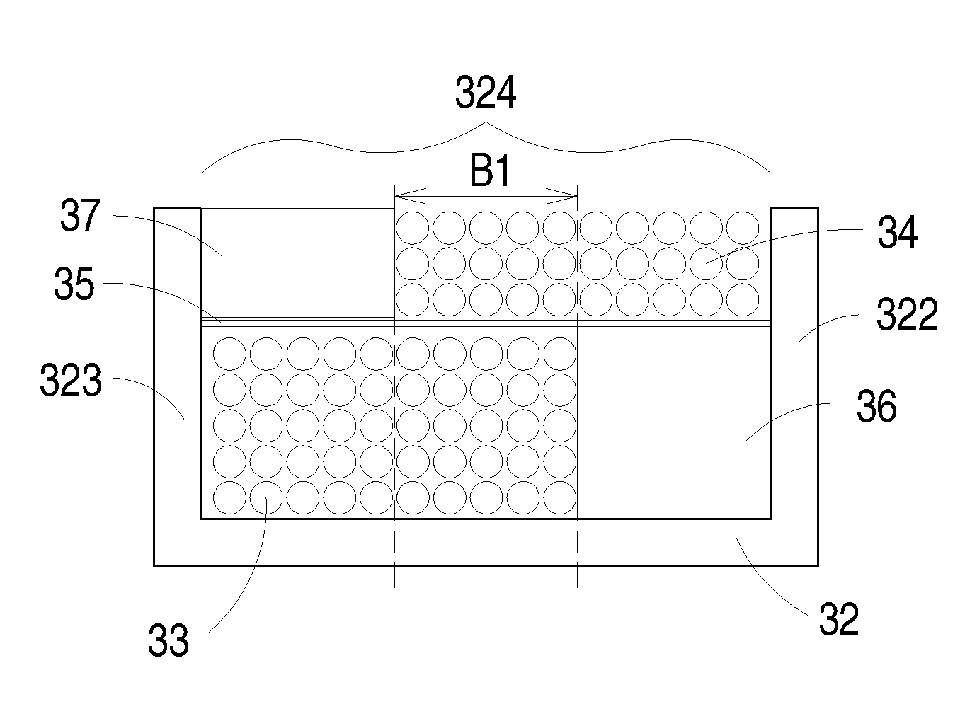
[0019]Referring to FIG. 3, a schematic exploded view of a transformer according to a preferred embodiment of the present invention is illustrated. FIG. 4 is a schematic cross-sectional view of the transformer taken along the cross-section A1A2A3A4. As shown in FIG. 3 and FIG. 4, the transformer 3 principally comprises a magnetic core assembly 31, a bobbin 32, a primary winding coil 33 and a secondary winding coil 34. The magnetic core assembly 31 of the transformer 3 includes a first magnetic part 311 and a second magnetic part 312, which are cooperatively formed as an EE-type core assembly, an EI-type core assembly, an ER-type c...


PUM

PropertyMeasurementUnit
leakage inductanceaaaaaaaaaa

Abstract

A transformer having adjustable leakage inductance includes a primary winding coil, a secondary winding coil, a bobbin and a magnetic core assembly. The bobbin includes a winding section for winding the primary winding coil and the secondary winding coil thereon, wherein the bobbin further includes a channel therein. The magnetic core assembly is partially embedded into the channel of the first bobbin. The primary winding coil and the secondary winding coil are partially overlapped with each other and wound around the winding section of the bobbin to be defined as an overlap region. The region where the primary winding coil and the secondary winding coil are not overlapped with each other is defined as a non-overlap region. The leakage inductance of the transformer is adjusted according to an overlap ratio of the overlap region to the sum of the overlap region and the non-overlap region.

Description

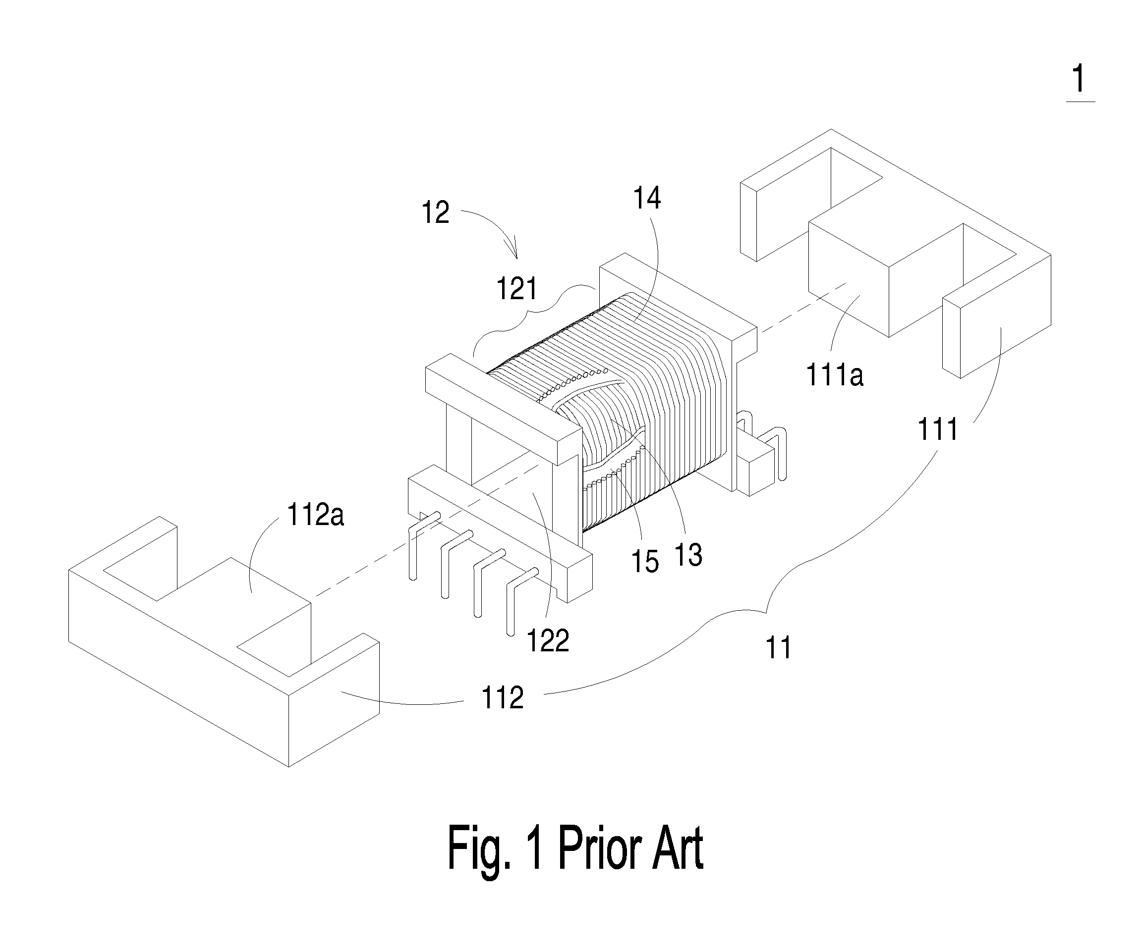
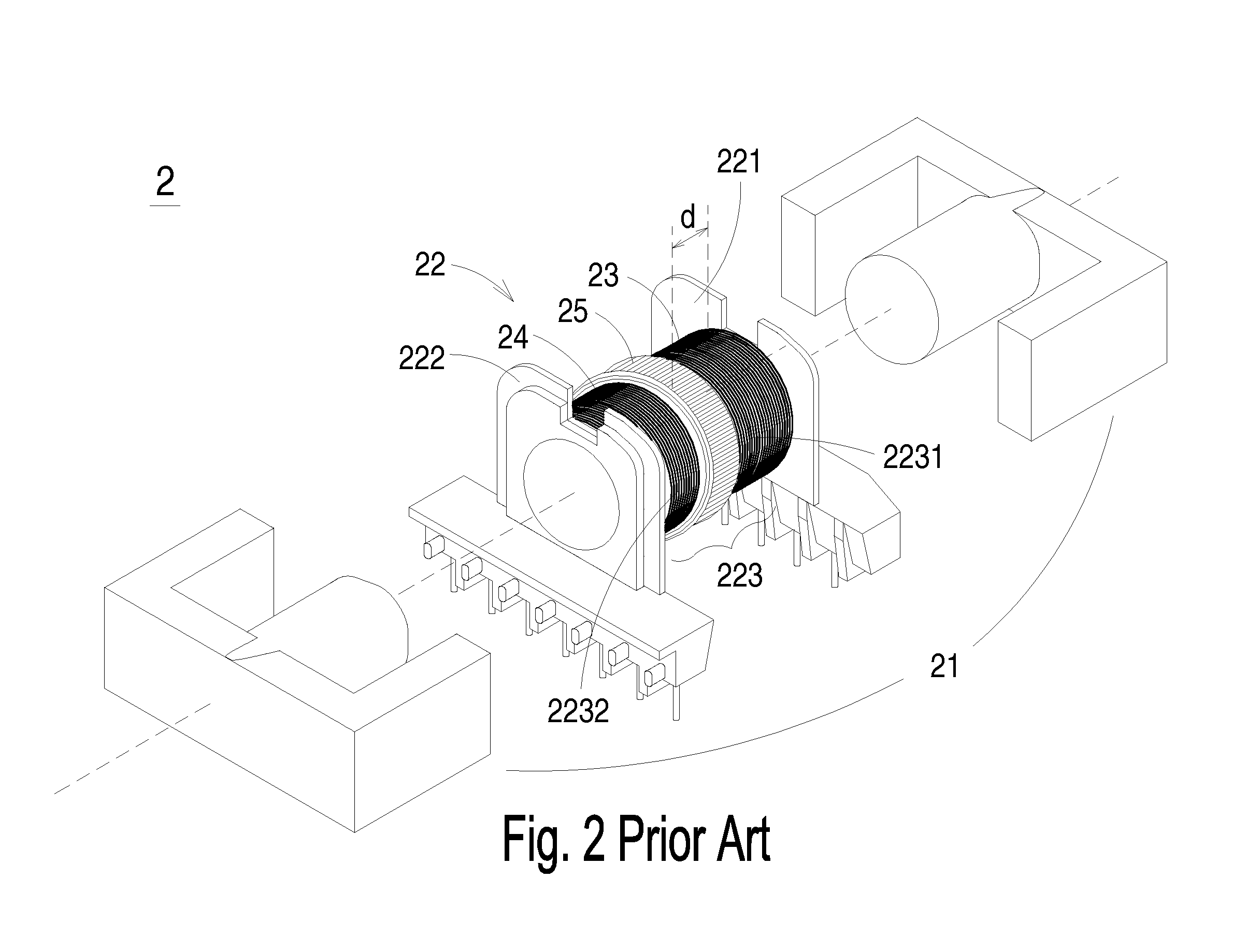
FIELD OF THE INVENTION[0001]The present invention relates to a transformer, and more particularly to a transformer having adjustable leakage inductance.BACKGROUND OF THE INVENTION[0002]A transformer has become an essential electronic component for various kinds of electric appliances. Referring to FIG. 1, a schematic exploded view of a conventional transformer is illustrated. The transformer 1 principally comprises a magnetic core assembly 11, a bobbin 12, a primary winding coil 13 and a secondary winding coil 14. The primary winding coil 13 and the secondary winding coil 14 are overlapped with each other and wound around a winding section 121 of the bobbin 12. A tape 15 is provided for isolation and insulation. The magnetic core assembly 11 includes a first magnetic part 111 and a second magnetic part 112. The middle portion 111a of the first magnetic part 111 and the middle portion 112a of the second magnetic part 112 are embedded into the channel 122 of the bobbin 12. The primary...

Claims


Application Information

Patent Timeline
Patent Type & Authority Patents(United States)
IPC IPC(8): H01F27/28
CPCH01F27/326H01F38/10H01F27/346H01F29/12
Inventor HSU, WEN-KUAN
Owner DELTA ELECTRONICS INC
Learn More