
System and method for remotely detecting and locating faults in a power system

a technology of power system and remote detection, applied in the field of remote detection and fault detection of power system faults, can solve the problems of aging wire strands, wires can become faulty, insulation can breakdown and chaff, etc., and achieve the effect of preventing interference to loads during operation

Inactive Publication Date: 2007-06-26
THE BOEING CO
View PDF13 Cites 53 Cited by
  • Summary
  • Abstract
  • Description
  • Claims
  • Application Information

AI Technical Summary

Benefits of technology

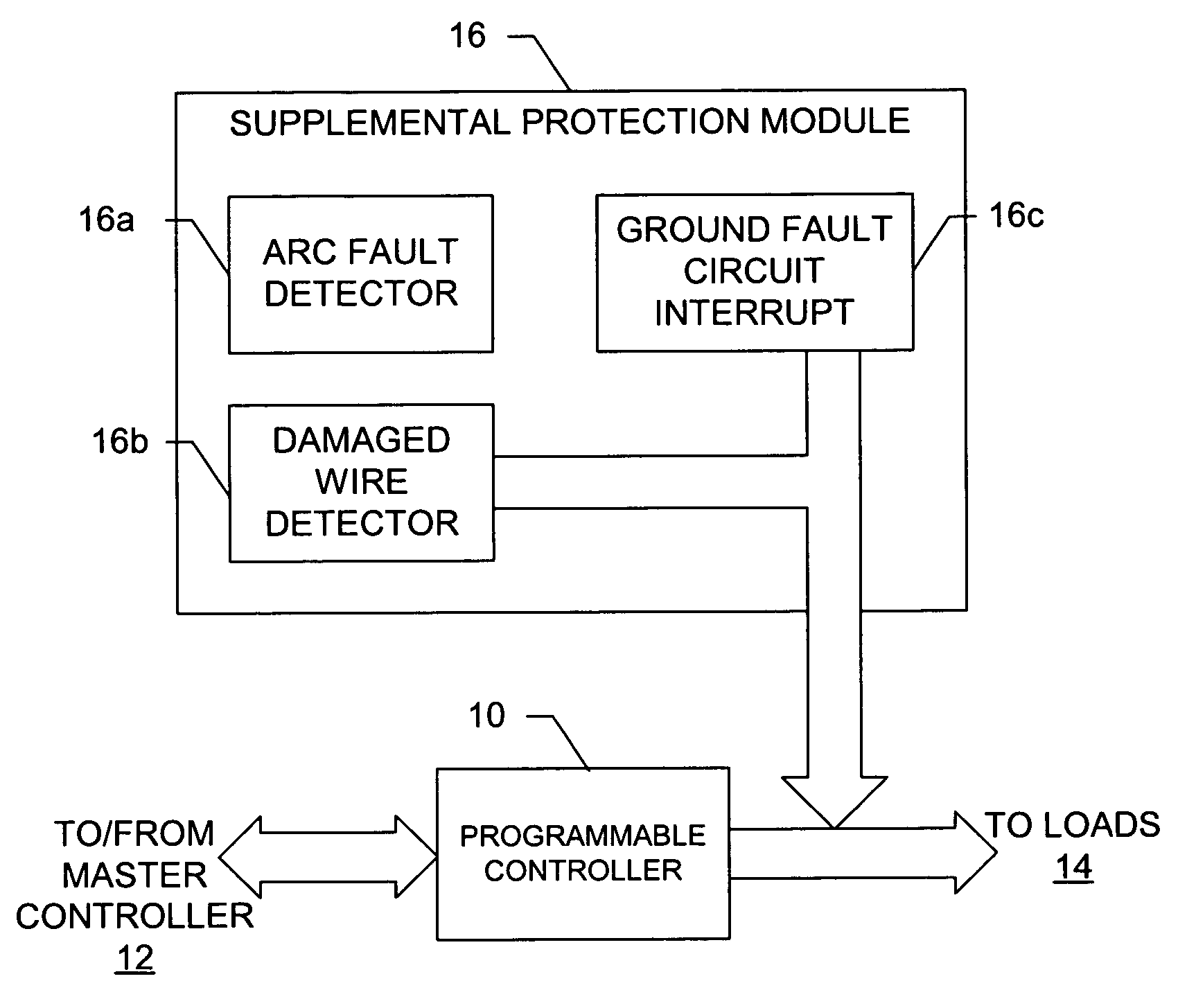
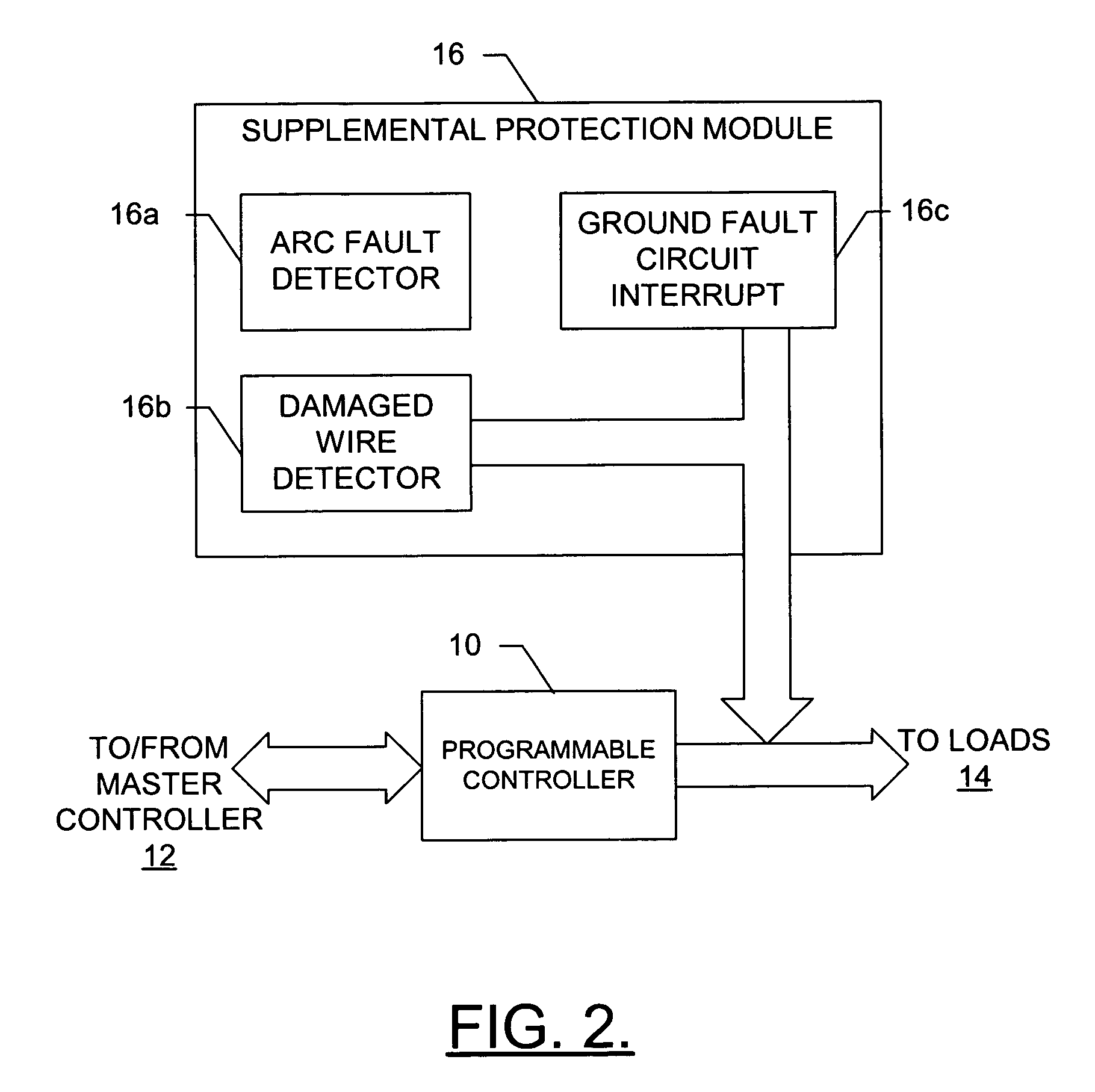
The present invention provides a system and method for locating faults in a power system. The system includes a slave controller and a supplemental protection module. The slave controller is disposed proximate to the loads and can detect and isolate faults in the conductors. The supplemental protection module can detect and locate faults, as well as monitor input current to the loads for abnormal current. The system can also detect and locate damaged conductors and electric arc events, and can prevent interference to loads. The technical effects of the invention include improved fault detection and location, as well as improved safety and reliability in power system operations.

Problems solved by technology

Although each wire is typically surrounded by insulation, or sheathing, such wires can become faulty.
In this regard, as the wires age, the insulation can breakdown and chaff.
Also, strands in aging wires can begin to separate and tear due to vibration, shock and stress on the wires.
Stress due to pinching, rubbing, moisture, corrosion, excessive heat and / or lightening strikes also pose risks that can lead to wire damage.
Further, tight fitting connection points within connectors can loosen over time when subjected to the same environmental conditions as the conductors, and when subjected to numerous connects and disconnects due to replacement and maintenance of the electrical components, systems, subsystems, and the electrical power systems.
As will be appreciated by those skilled in the art, when the insulation surrounding the wires breaks down or chaffs, or the wire otherwise becomes faulty, undesirable electric arcs or other wire breakdown can occur at one or more locations along the wires, which can lead to breaks or shorts in the system.
Also, an arc event may only brown an area of occurrence without actually burning through or burning the insulation away form the affected wire.
In many instances, detecting and locating the arc event or other wire breakdown can be difficult, if not impossible.
In this regard, detecting a fault in the system as being caused by a faulty wire may be difficult in systems that also include complex electrical components, systems, subsystems and power systems.
As such, misdiagnosing a fault in the system as being caused by costly electrical components, for example, can result in unnecessary replacement of such components while still failing to correct the fault.
In addition to the difficulty in detecting an arc event or other wire breakdown, locating such an arc event or other breakdown is also difficult.
In many instances, the location of the arc event or other breakdown may be in a location that is impossible to visually locate without extracting a wire bundle from the system.
However, inspection of many feet of wire within a system can be very time consuming, and in some cases, may place maintenance personnel at risk for injury.
Also, most conventional wire testing equipment is cumbersome and requires unique training of maintenance personnel as to how to use the equipment.
Unnecessary removal of equipment can also be very costly and time consuming, however, and can add to the required time to perform maintenance on the system.
Further, many times such connection points are not located in easily accessed locations.

Method used


Image

  • System and method for remotely detecting and locating faults in a power system
  • System and method for remotely detecting and locating faults in a power system
  • System and method for remotely detecting and locating faults in a power system

Examples


Embodiment Construction

[0026]The present invention now will be described more fully hereinafter with reference to the accompanying drawings, in which preferred embodiments of the invention are shown. This invention may, however, be embodied in many different forms and should not be construed as limited to the embodiments set forth herein; rather, these embodiments are provided so that this disclosure will be thorough and complete, and will fully convey the scope of the invention to those skilled in the art. Like numbers refer to like elements throughout.

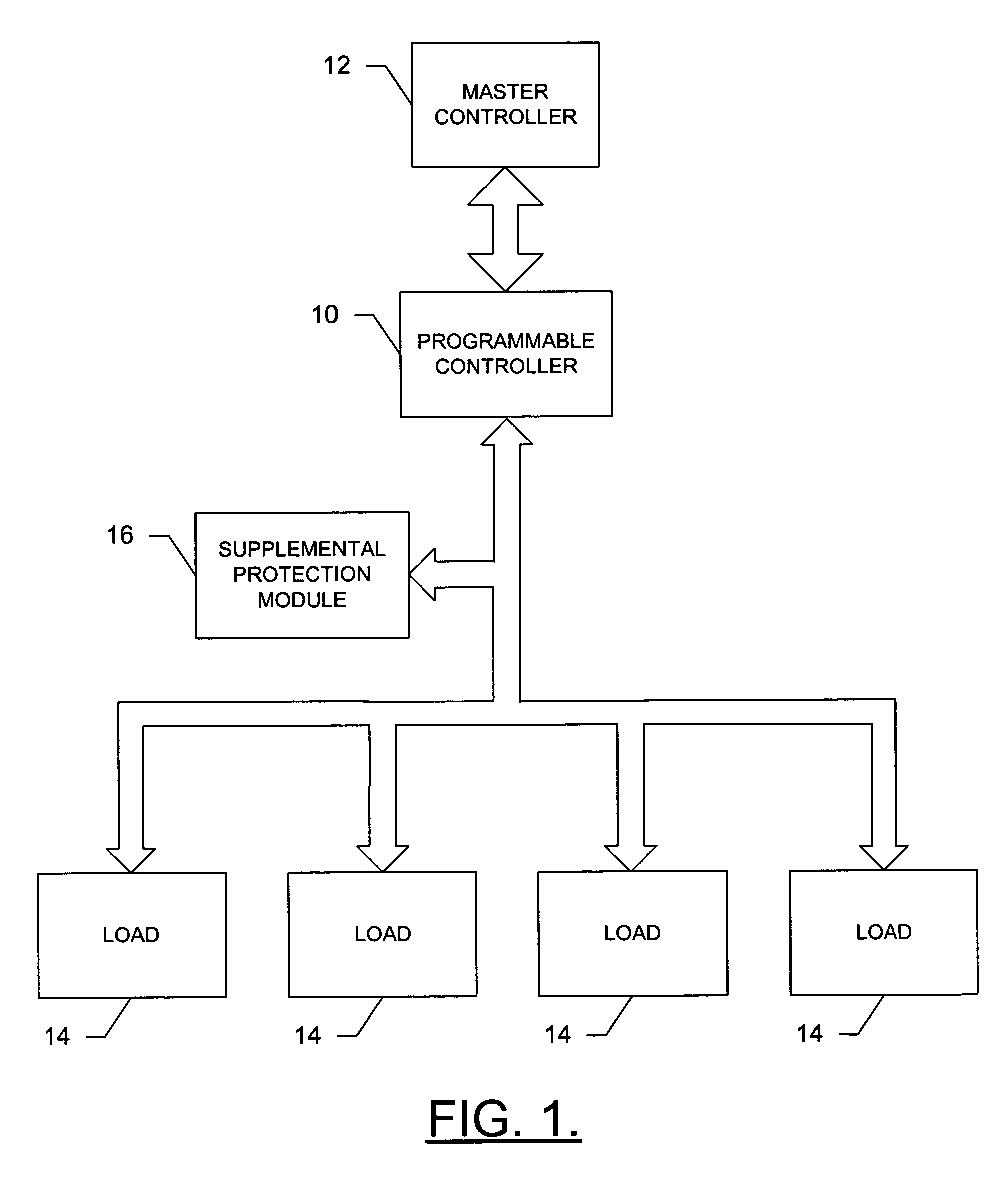
[0027]FIG. 1 is an illustration of a system that would benefit from the damaged wire detector of one embodiment of the present invention. This illustration is provided so that a more complete understanding of the present invention may be appreciated. It must be understood that the present invention is not limited to this configuration and may be embodied in many different power systems.

[0028]With regard to FIG. 1, a general embodiment of a power system in ...


PUM


Abstract

A system and method are provided for remotely detecting and locating faults in a power system. The system includes at least one slave controller and at least one supplemental protection module. The slave controller is disposed proximate at least one load and electrically connected to the loads via at least one conductor. More particularly, the slave controller includes at least one solid-state switch capable of controllably altering the input current to the loads. The slave controller also includes at least one measuring element for measuring at least one parameter associated with the loads and the solid-state switches. The solid-state switch can then controllably alter the input current to the loads according to the parameter. The supplemental protection modules are electrically connected to the conductors between the slave controller and the loads. In this regard, the supplemental protection modules can detects at least one fault in at least one conductor.

Description

FIELD OF THE INVENTION[0001]The present invention relates generally to power system maintenance and, more particularly, to a system and method for remotely detecting and locating faults in a power system.BACKGROUND OF THE INVENTION[0002]In many industries today, such as the avionics and automotive industries, complex and costly electrical components, systems and subsystems, as well as the electrical power systems powering these components, are interconnected by many bundles of conductors, typically wires, with each bundle including a plurality of wires. Although each wire is typically surrounded by insulation, or sheathing, such wires can become faulty. In this regard, as the wires age, the insulation can breakdown and chaff. In such instances, the wires can contact other wires or other conductive structures, such as framework. Also, strands in aging wires can begin to separate and tear due to vibration, shock and stress on the wires. Stress due to pinching, rubbing, moisture, corro...

Claims


Application Information

Patent Timeline
Patent Type & Authority Patents(United States)
IPC IPC(8): H02H3/00G01R31/08H02H1/00H02H3/093H02H3/33H02H5/10
CPCH02H1/0015H02H5/10G01R31/086G05B2219/14003H02H3/0935H02H3/33
Inventor HALE, CHRISTOPHER L.HORNSBY, RODNEY M.MAXWELL, JR., JOHN M.SCHWARZ, CHARLES R.
Owner THE BOEING CO
Learn More