Feed assembly for multi-beam antenna with non-circular reflector, and such an assembly that is field-switchable between linear and circular polarization modes

a multi-beam antenna and reflector technology, applied in the field of antennas, can solve the problems of elliptical reflectors, not maintaining symmetry, and not being practicable for most customers, and achieve the effect of facilitating the close proximity of the two feeds, reducing the overall size, and facilitating the close spacing of the feeds

Inactive Publication Date: 2007-06-26
CPI SATCOM & ANTENNA TECH INC
View PDF79 Cites 35 Cited by
  • Summary
  • Abstract
  • Description
  • Claims
  • Application Information

AI Technical Summary

Benefits of technology

[0021]The feed assembly can also include a separate second feed positioned closely adjacent the feed horn for establishing a communications link with a second satellite (e.g., a BSS satellite or another FSS satellite) spaced as close as 2 degrees from the first satellite (e.g., an FSS satellite). One or both of the first feed horn and the second feed horn can contain a dielectric having a dielectric constant greater than 1.0 so as to allow the dimensions of the feed(s) to be reduced to facilitate the required close proximity of the two feeds. Either or both of the feeds may be filled with a dielectric material to reduce their overall size as is described in U.S. Pat. No. 6,480,165 to thereby facilitate close spacing of the feeds.
[0022]The feed assembly includes a coupling arrangement that rotatably couples the polarizer and the circular waveguide section of the feed horn. In one embodiment of the invention, the circular waveguide section of the feed horn has a radially outwardly projecting flange formed proximate the end of the circular waveguide section that connects to the polarizer. The polarizer comprises a substantially circular cylindrical main body having a first end adjacent the flange and an opposite second end, the main body having a radially outwardly projecting first ring formed proximate the first end of the main body. The coupling arrangement includes a first coupler structured and arranged to engage the first ring on the polarizer and the flange on the circular waveguide section so as to substantially prevent relative axial movement therebetween while permitting the polarizer to rotate relative to the circular waveguide section.

Problems solved by technology

Unfortunately, many related services are offered on different satellites.
While this can be accomplished using different antennas corresponding to each satellite, this solution is neither practical nor acceptable for most customers.
There are various issues associated with the design of multi-beam antennas.
One such issue is reflector profile.
While use of a reflector having an elliptical profile allows multiple feeds to be placed in the same antenna solution, there are some drawbacks to use of these reflectors.
Elliptical reflectors, on the other hand, do not maintain this symmetry because of their different dimensions in the horizontal and vertical directions.
Thus, elliptical reflectors are typically not used with circular polarized communications, thereby making it difficult to provide a multi-beam solution where at least one of the satellites communicates using circularly polarized signals.
An additional issue with multi-beam solutions is satellite position spacing.
The proximity of these satellites to each other is somewhat problematic from the standpoint of using one antenna to establish individual communication links with both of these satellites.
The problem is that many conventional corrugated wave-guide designs cannot be used, because of the reduced spacing required between the phase centers of the wave-guides needed to receive from and transmit signals to the satellites is such that the conventional individual wave-guides would occupy overlapping space due to their size.
However, there are other issues yet to be addressed.
An added issue with multi-beam antenna solutions is the transition from use of satellites that communicate using linear polarization to satellites that communicate using circular polarized signals, or visa versa.
This, unfortunately, is not a viable solution.
However, the reflector ellipticity destroys the system symmetry as required for circularly polarization and creates a high level of axial ratio or cross-polarization.

Method used


Image

  • Feed assembly for multi-beam antenna with non-circular reflector, and such an assembly that is field-switchable between linear and circular polarization modes
  • Feed assembly for multi-beam antenna with non-circular reflector, and such an assembly that is field-switchable between linear and circular polarization modes
  • Feed assembly for multi-beam antenna with non-circular reflector, and such an assembly that is field-switchable between linear and circular polarization modes

Examples


Embodiment Construction

[0033]The present inventions now will be described more fully hereinafter with reference to the accompanying drawings, in which some, but not all embodiments of the invention are shown. Indeed, these inventions may be embodied in many different forms and should not be construed as limited to the embodiments set forth herein; rather, these embodiments are provided so that this disclosure will satisfy applicable legal requirements. Like numbers refer to like elements throughout.

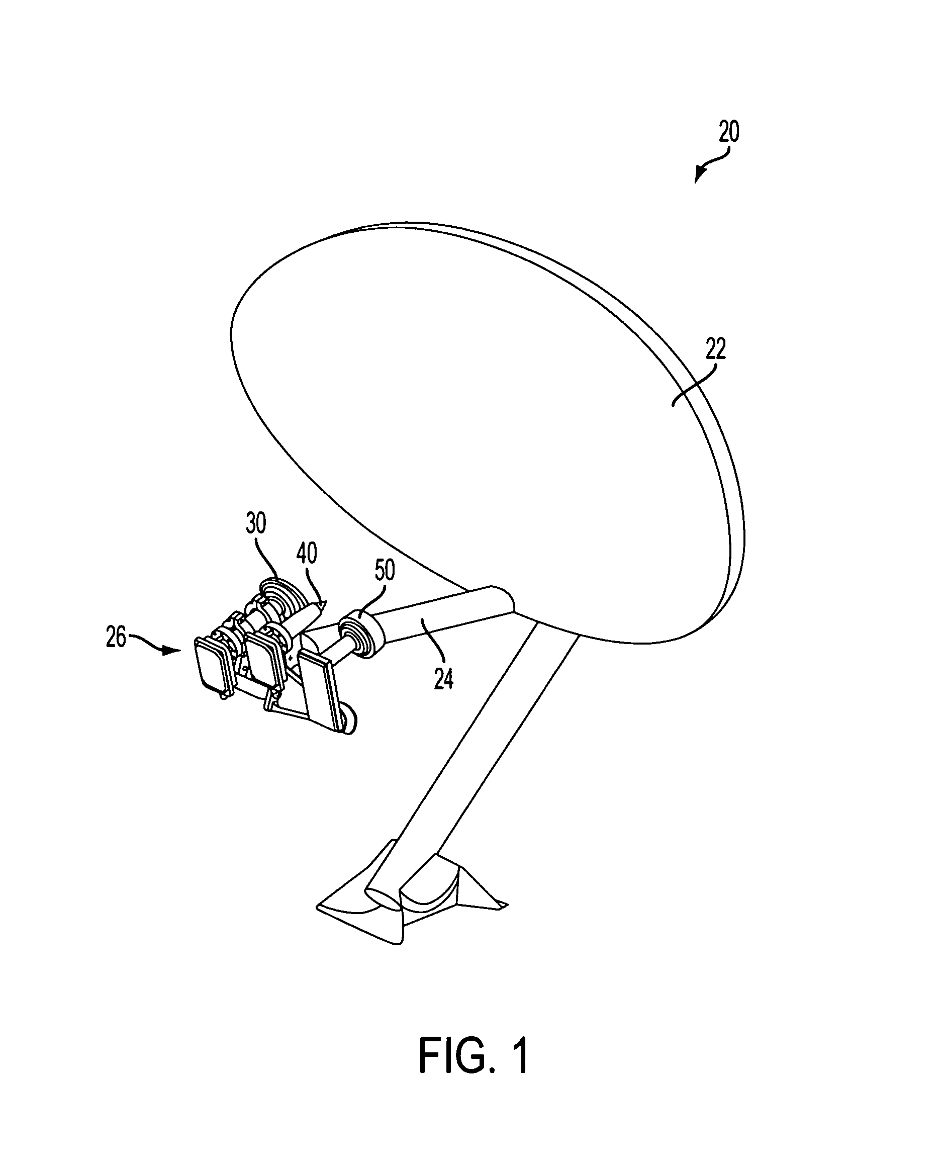
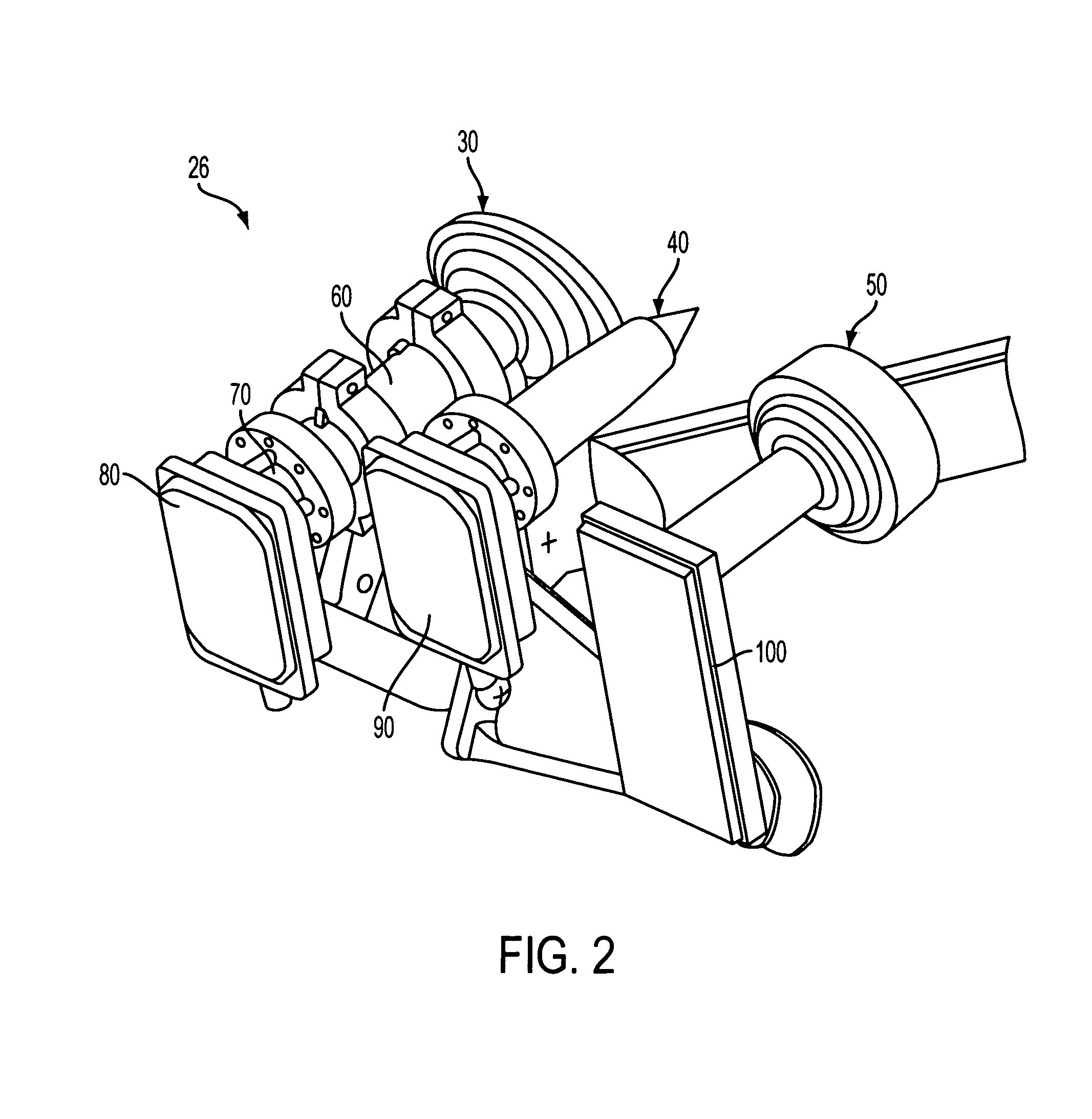
[0034]A multi-beam antenna 20 in accordance with one embodiment of the invention is shown in FIG. 1. The antenna includes a reflector 22 of non-circular profile; in the illustrated embodiment, the reflector has an elliptical profile, but the invention is not limited to such profile. It also applies to any geometry having aspect ratio larger than 1. Mounted on a boom 24 in front of the reflector is a feed assembly 26 having three feeds for establishing three separate communication links with three different sate...


PUM


Abstract

A feed assembly for an antenna having a non-circular reflector, in which the feed assembly includes a feed horn capable of correcting the distortions of circularly polarized signals caused by the non-circular reflector profile, and wherein the feed horn is coupled with a polarizer that is field-switchable between linear and circular polarization modes of operation. The feed assembly can include a second receive-only feed located in close proximity to the feed horn for communication with adjacent satellites.

Description

CROSS-REFERENCE TO RELATED APPLICATIONS[0001]The present application claims priority from U.S. Provisional Application Ser. No. 60 / 505,784 entitled FEED ASSEMBLY FOR MULTI-BEAM ANTENNA WITH NON-CIRCULAR REFLECTOR, AND SUCH AN ASSEMBLY THAT IS FIELD-SWITCHABLE BETWEEN LINEAR AND CIRCULAR POLARIZATION MODES, filed Sep. 25, 2003, the contents of which are incorporated herein by reference.FIELD OF THE INVENTION[0002]The invention relates to antennas for establishing communication links with satellites in geostationary orbit about the earth. The invention relates in particular to an antenna having a non-circular reflector and a feed assembly that is field-switchable between circularly polarized and linearly polarized operating modes, and to a multi-beam antenna having a non-circular reflector and a feed assembly that is capable of establishing communications with two or more satellite, where at least two of the satellites are closely spaced.BACKGROUND OF THE INVENTION[0003]An increasing ...

Claims


Application Information

Patent Timeline
Patent Type & Authority Patents(United States)
IPC IPC(8): G02B6/00H01Q13/02
CPCH01Q13/025H01Q13/0258
Inventor MOHEB, HAMIDPENLEY, MICHAEL L.
Owner CPI SATCOM & ANTENNA TECH INC
Why Eureka
Try Eureka