Check patentability & draft patents in minutes with Patsnap Eureka AI!

Shielded connector

a shielding connector and connector technology, applied in the direction of coupling device connection, coupling parts engagement/disengagement, electrical apparatus, etc., can solve the problems of large clearances produced between the arcuate portions of the connection shell, and noise can leak to the outside through these clearances, so as to suppress the leakage of noise through the clearance between the connection shell and the housing shell

Inactive Publication Date: 2007-07-03
SUMITOMO WIRING SYST LTD
View PDF15 Cites 21 Cited by
  • Summary
  • Abstract
  • Description
  • Claims
  • Application Information

AI Technical Summary

Benefits of technology

The design effectively suppresses noise leakage by ensuring a secure overlap between the housing and connection shells, maintaining a crimping area free from angled portions, and providing a visual confirmation of secure fastening, thus enhancing noise shielding and connector stability.

Problems solved by technology

Thus, large clearances unavoidably are produced between the arcuate portions of the connection shell and the angled portions of the housing shell when connecting a rectangular housing shell to a connection shell that has large arcuate portions.
Noise can leak to the outside through these clearances.

Method used


Image

  • Shielded connector
  • Shielded connector
  • Shielded connector

Examples


Embodiment Construction

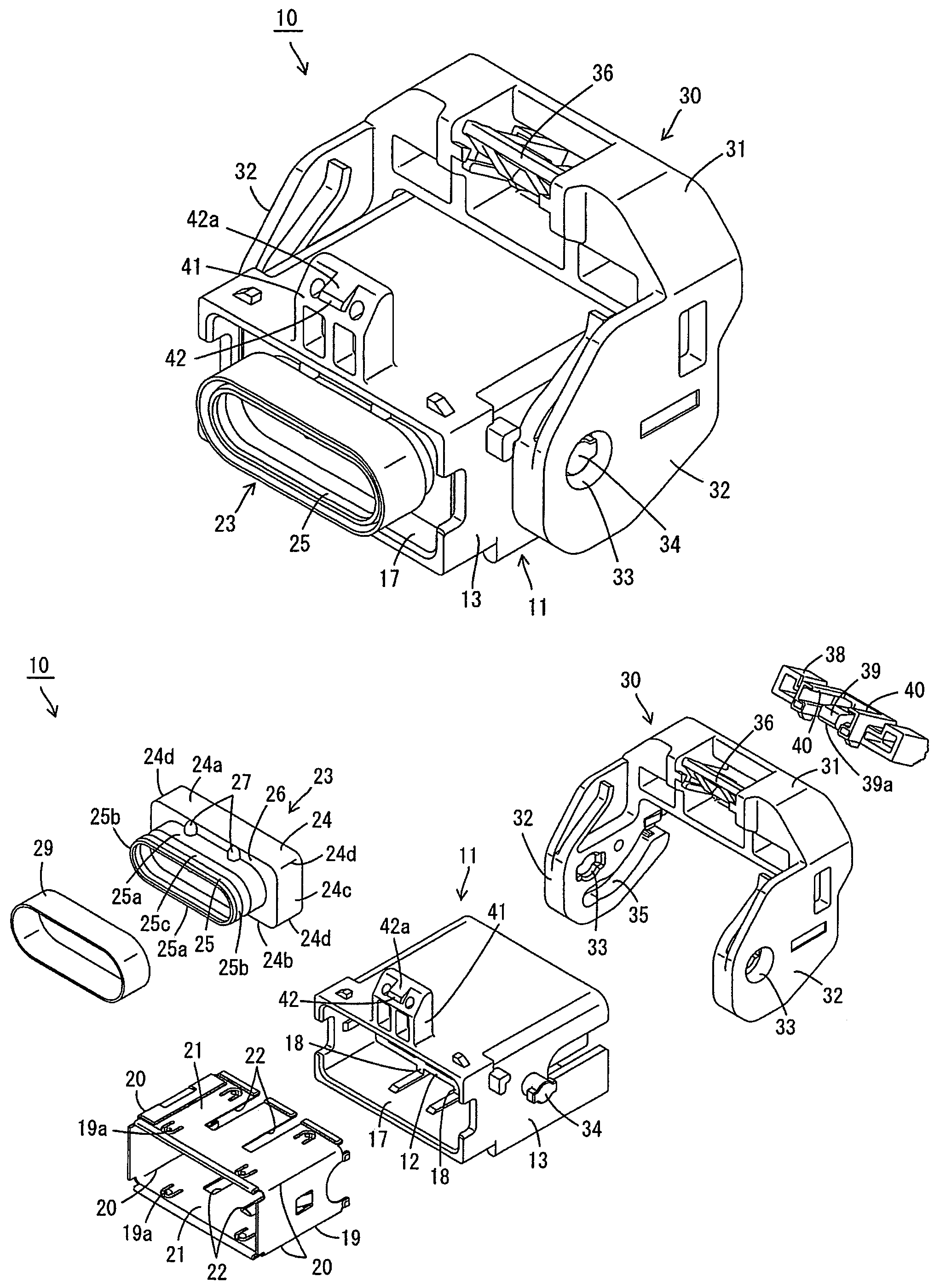
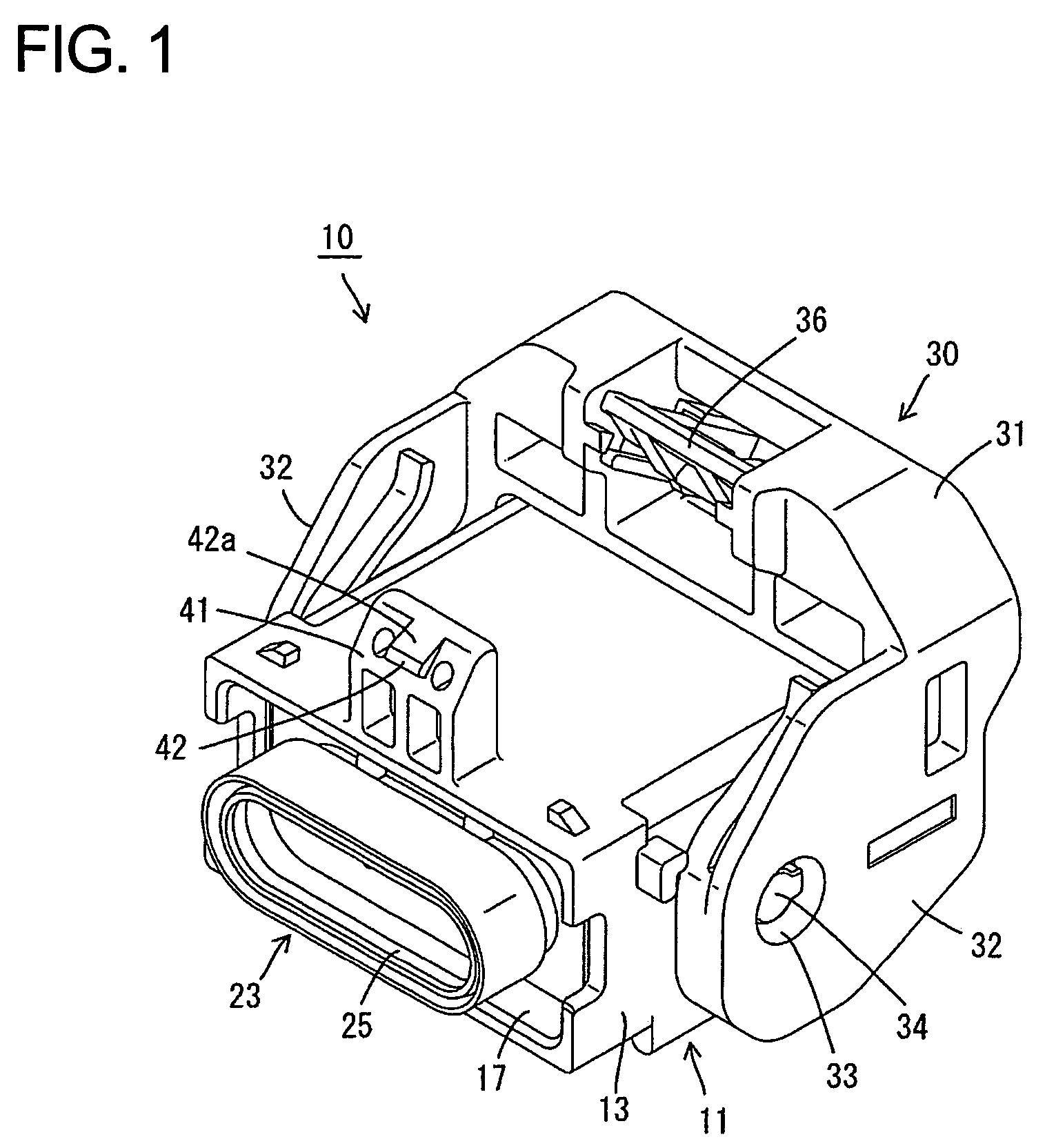
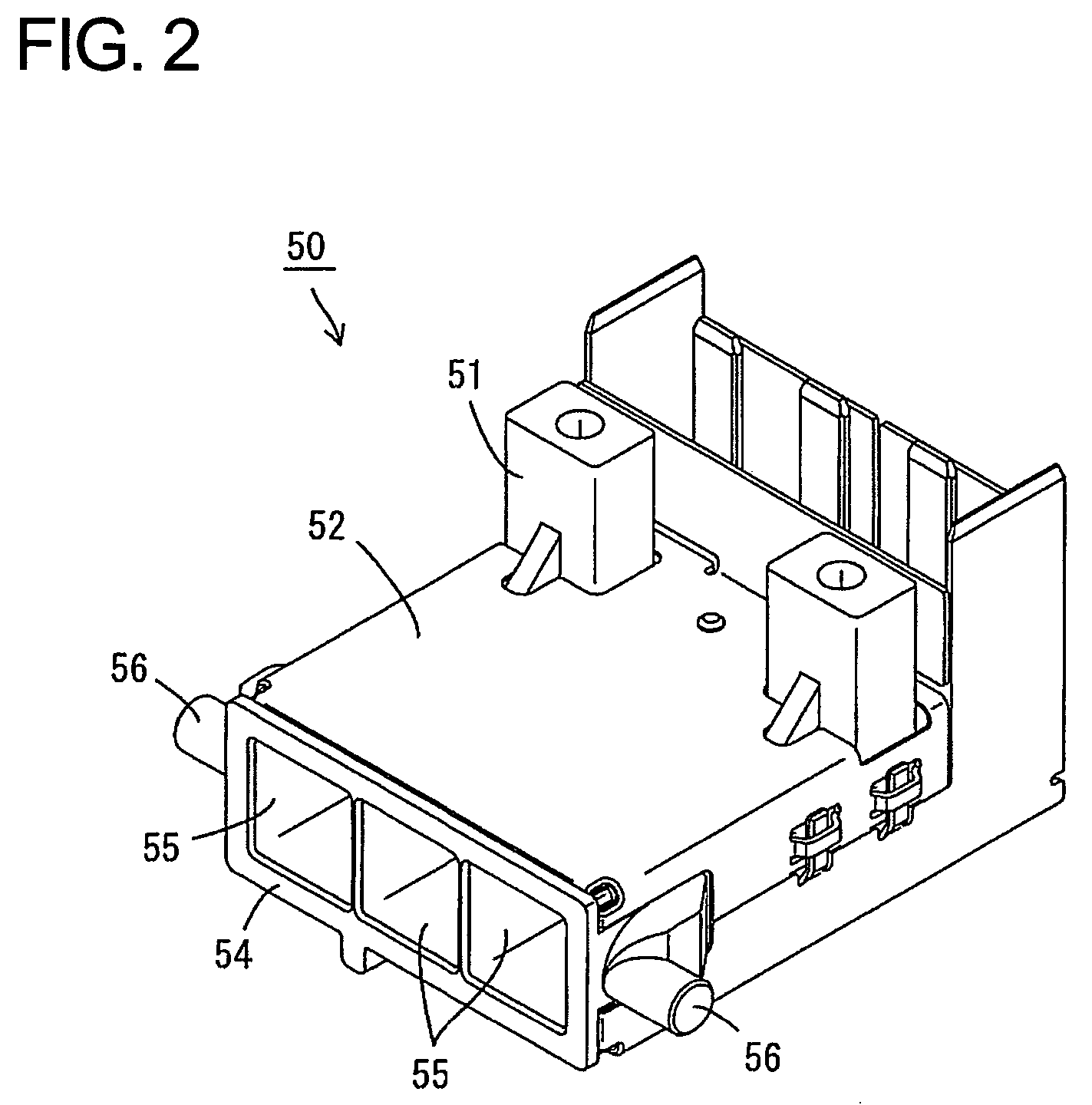
[0036]A shielded connector assembly in accordance with the invention is described with reference to FIGS. 1 to 13. The assembly includes first and second shielded connectors 10 and 50 that are connectable with each other.

[0037]The first shielded connector 10 includes a first housing 11 that is molded unitarily e.g. of a synthetic resin and has block-shaped terminal accommodating portions 12 arranged substantially side by side and coupled to each other at their rear ends. The first housing 11 also has a substantially rectangular tubular fitting 13 that surrounds the terminal accommodating portions 12. First terminal fittings 14 are inserted into the respective terminal accommodating portions 12 from behind and wires 15 are connected with the rear ends of the respective first terminal fittings 14 by crimping, bending, folding, insulation displacement, soldering or the like. Each wire 15 is unshielded and has a core surrounded by an insulation coating. The wires 15 are drawn out throug...


PUM


Abstract

A connection shell (23) includes a tubular fastener (25) formed by flat surfaces (25a) and curved surfaces (25b) and a rectangular tubular contact (24). A crimp ring (29) is crimped to fasten a wire shield (28) to the outer peripheral surface of the tubular fastener (25). The tubular contact (24) is connected so that a circumferential surface thereof overlaps a circumferential surface of a housing shell (19). The tubular contact (24) has a rectangular shape that conforms with the rectangular tubular shape of the housing shell (19). Thus, only a small clearance is defined between the housing shell (19) and the connection shell (23) to suppress leakage of noise through the clearance between the housing shell (19) and the connection shell (23).

Description

BACKGROUND OF THE INVENTION[0001]1. Field of the Invention[0002]The present invention relates to a shielded connector.[0003]2. Description of the Related Art[0004]Japanese Unexamined Patent Publication No. 2002-319458 discloses a shielded connector that has terminal fittings accommodated in a housing made of synthetic resin. A metallic tubular shell is assembled to the housing and substantially surrounds the housing for shielding. The housing shell absorbs noise from the terminal fittings to prevent leakage of the noise from the housing.[0005]A braided wire shield surrounds the wires drawn from the housing to shield the wires together, and a metallic tubular shielding connection shell connects the wire shield and the housing shell. The connection shell and the housing shell are brought into contact so that their peripheral surfaces overlap.[0006]The wire shield is connected with the connection shell by crimping a crimp ring. A crimp ring with an oblong or elliptical shape is conside...

Claims


Application Information

Patent Timeline
Patent Type & Authority Patents(United States)
IPC IPC(8): H01R9/03H01R13/648
CPCH01R9/032H01R13/6593H01R9/05H01R9/0518H01R13/62938H01R13/6295H01R13/6582H01R13/65912
Inventor SAKAKURA, KOUJISHINOZAKI, TETSUYA
Owner SUMITOMO WIRING SYST LTD
Features
  • R&D
  • Intellectual Property
  • Life Sciences
  • Materials
  • Tech Scout
  • Unparalleled Data Quality
  • Higher Quality Content
  • 60% Fewer Hallucinations
Learn More