Ball catching and delivery frame with variable flex sidewalls

Active Publication Date: 2007-07-03
CASCADE MAVERIK LACROSSE LLC
View PDF12 Cites 58 Cited by
  • Summary
  • Abstract
  • Description
  • Claims
  • Application Information

AI Technical Summary

Benefits of technology

[0010]In still a further embodiment, the flex region is defined by respective pivotally connected fore and aft frame members. Stiffeners adapted to enhance the lateral stiffness of the frame are de

Problems solved by technology

Thus, the resiliency and flexing capability of the sidewalls is disadvantageous

Method used


Image

  • Ball catching and delivery frame with variable flex sidewalls
  • Ball catching and delivery frame with variable flex sidewalls
  • Ball catching and delivery frame with variable flex sidewalls

Examples


first embodiment

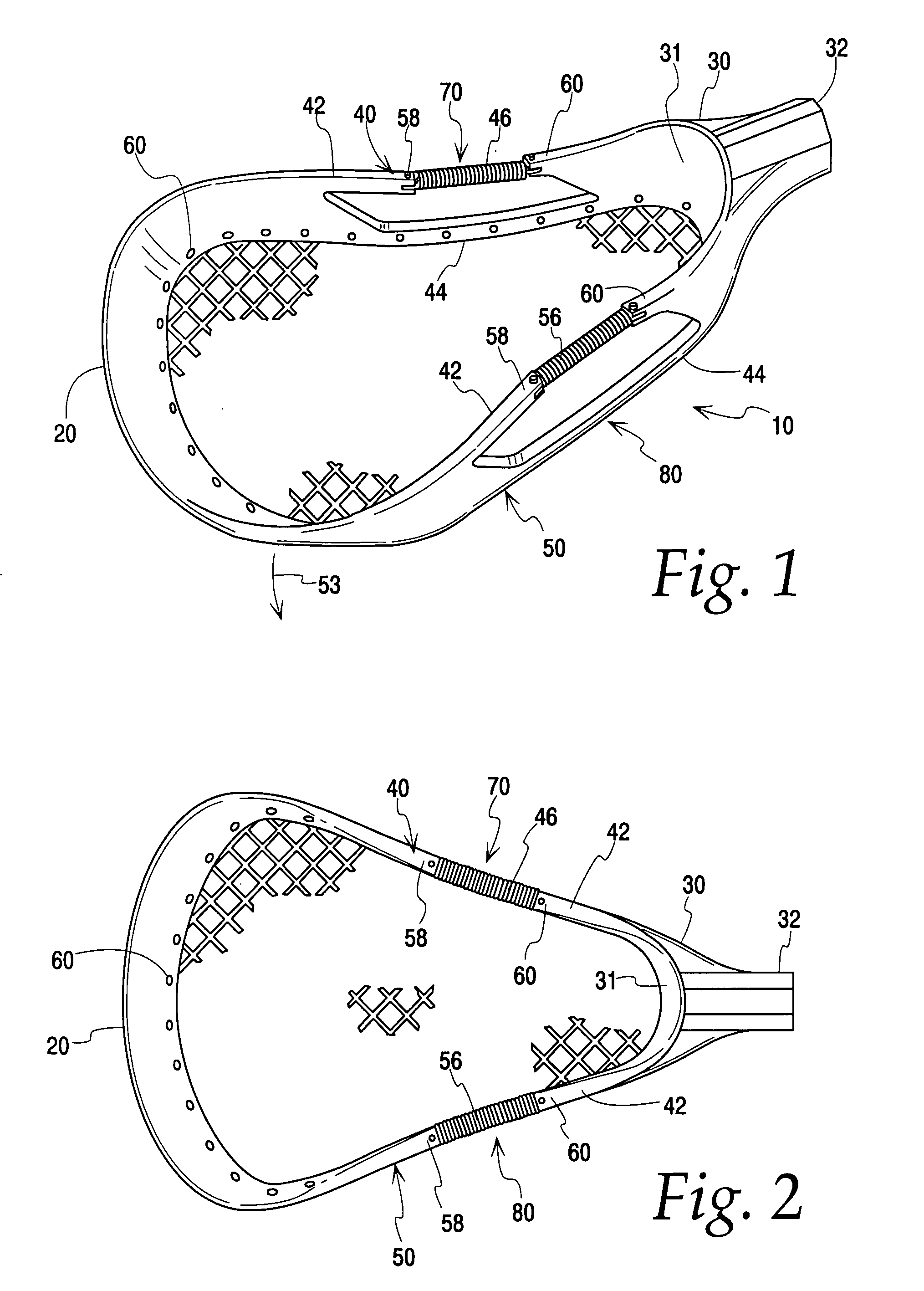
[0024]FIGS. 1-3 depict the invention in the form of a frame for a lacrosse head, the frame 10 having a front or scoop wall 20, a rear base 30 including a back stop wall 31 and a hollow sleeve or socket 32 adapted to receive the end of a handle or stick (not shown), and lateral sides or walls 40 and 50 extending unitarily between the base 30 and scoop wall 20. The back stop wall 31, sidewalls 40 and 50, and scoop wall 20 together define the periphery of a ball receiving and delivery face, the upper side of which is shown in FIGS. 1 and 2. Presently preferred materials from which the frame may be manufactured include fiber reinforced thermoplastic or thermoset plastics. Suitable examples include, but are not limited to, graphite, nylon and those materials sold under the trademark Santoprene™.

[0025]The frame 10 may include conventional known means such as holes or eyelets 60 for attaching a net or webbing (shown in broken fashion in FIGS. 1-3) to the frame 10. Alternatively, and althou...

second embodiment

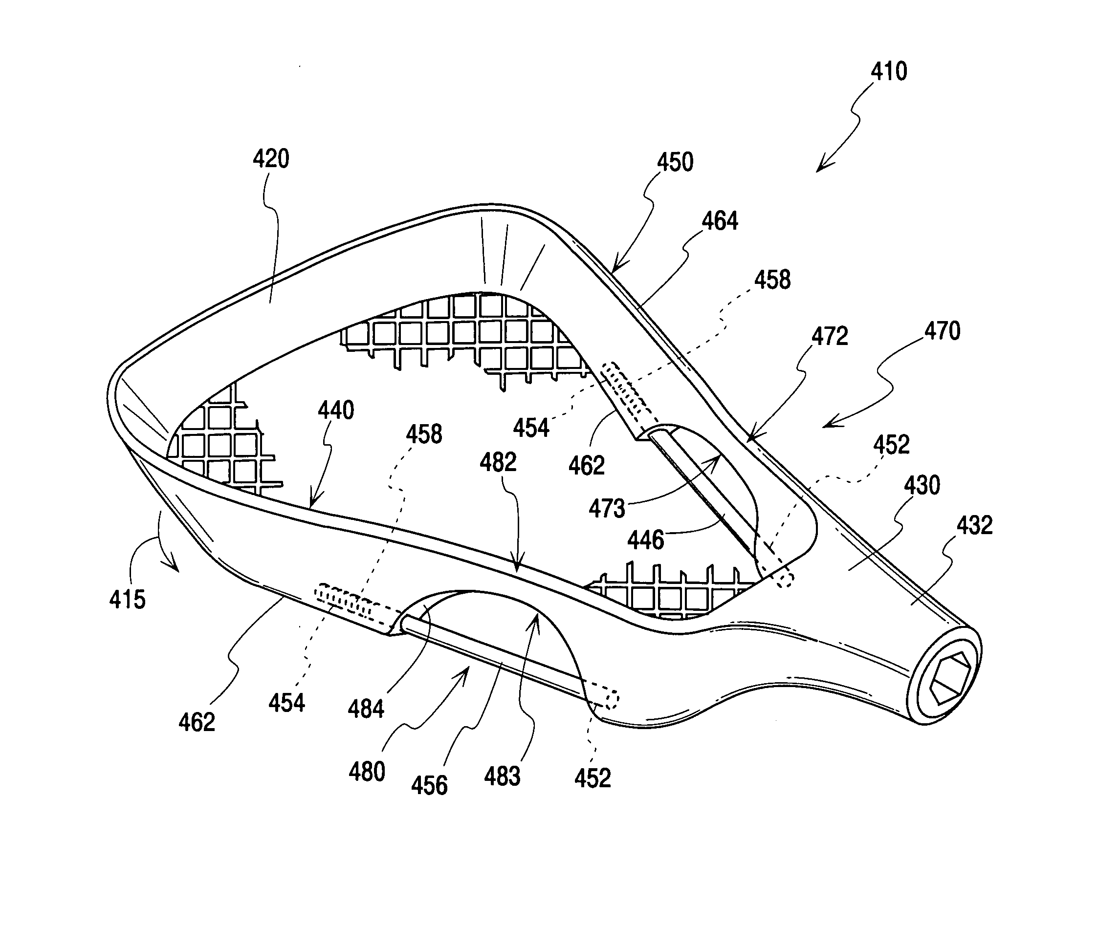
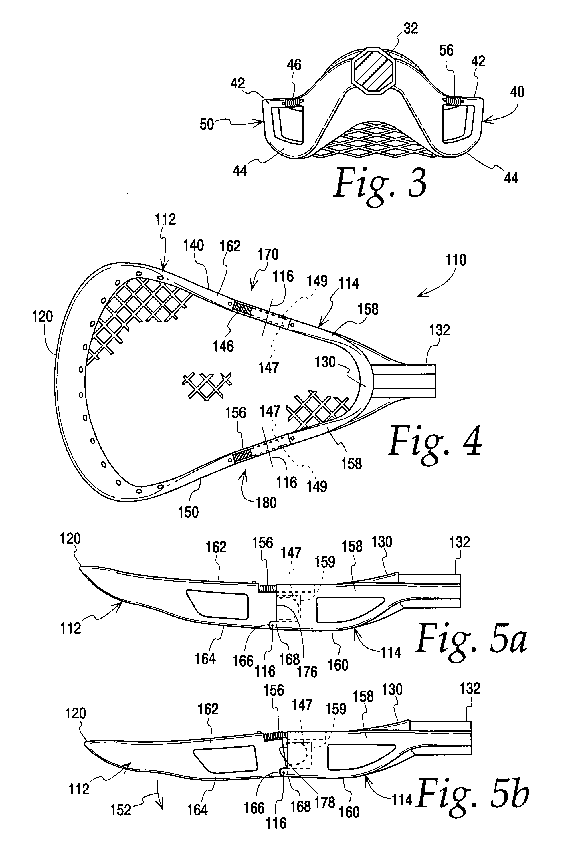
[0029]FIGS. 4, 5a and 5b depict a second embodiment, also depicted in the form of a lacrosse head frame 110, in which the frame 110 includes flexible sidewall regions 170 and 180 defined by pivotally connected independent fore and aft frame / sidewall members 112 and 114 respectively which permit movement and flexing of the scoop 120 and fore frame member 112 with respect to, independent of, and relative to the aft frame member 114 and base 130 about pivot axes 116 in an up and down direction generally transverse to the frame longitudinal axis (see the arrow 152 in FIG. 5b). The fore frame member 112 incorporates the scoop 120 and the aft frame member 114 incorporates the base 130 and sleeve 132. In this embodiment, the aft frame member 114 and, more particularly, the portion of the sidewalls 140 and 150 defining the aft frame member 114 define respective upper and lower sidewall arms / edges 158 and 160 respectively while the fore frame member 112 and the portion of the sidewalls 140 a...

embodiment 210

[0032]FIG. 6 depicts an exploded perspective view of another lacrosse head frame embodiment 210 in which the lateral sidewalls 240 and 250 thereof include respective fore and aft frame / sidewall sections 212 and 214 wherein the height / cross-section of the sidewalls 240 and 250 in the region of the aft section 214 is about half or less than half of the height / cross-section of the respective sidewalls 240 and 250 in the fore section 212 so as to define respective arcuate elongate recesses, depressions or indentations 222 and 224 extending downwardly from the upper edge 226 of each of the sidewalls 240 and 250 and into the body 228 thereof in the region of the aft sidewall section 214. The distal ends of the respective portions of the sidewalls 240 and 250 defining the fore frame / sidewall section 212 extend into the scoop wall 220 while the proximal ends of the respective portions of the sidewalls 240 and 250 defining the aft sidewall section 214 extend into the base 230 of frame 210. T...


PUM


Abstract

A frame for a ball catching and delivery head for use in, for example, the sport of lacrosse comprising a frame having a scoop, a base and spaced lateral sidewalls therebetween defining the periphery of a ball receiving and delivery face. Each of the lateral sidewalls includes a flex region which is more elastically compliant and resilient than the remainder of the frame. In one embodiment, the flex regions define regions of the sidewalls comprised of a material which is more flexible than the material comprising the remainder of the frame. In another embodiment, the flex regions are defined by springs incorporated into the sidewalls. In a further embodiment, the flex regions are defined by regions of the sidewalls of reduced height and cross-section. In a further embodiment, the sidewalls comprise separate, pivotable aft and fore frame/sidewall members.

Description

FIELD OF THE INVENTION[0001]The present invention relates to sports in which balls are caught and thrown using hand held or stick mounted scoops or frames such as may be used in jai lai and the sport of lacrosse and, more particularly, to a frame or head for a lacrosse stick in which the sidewalls thereof are adapted for flexing action.BACKGROUND OF THE INVENTION[0002]A ball catching and delivery frame, scoop or head of the type used in the sport of lacrosse and relating to the subject of the present invention is most typically made of injection-molded, monolithic, durable and rigid material such as, for example, nylon, urethane, or polycarbonate. Examples of lacrosse heads are disclosed in, for example, the following U.S. patents: U.S. Pat. No. 5,290,039 issued Mar. 1, 1994 to Cornelio; U.S. Pat. No. 5,568,925 issued Oct. 29, 1996 to Morrow, et al.; U.S. Pat. No. 5,566,947 issued Nov. 3, 1998 to Tucker, et al.; and U.S. Pat. No. 6,066,056 issued May 23, 2000 to Morrow.[0003]The fle...

Claims


Application Information

Patent Timeline
IPC IPC(8): A63B59/02A63B65/12
CPCA63B59/02A63B59/0088A63B2243/005A63B59/20A63B60/50A63B2102/14
Inventor FILICE, GARYMEYER, DEAN E.
Owner CASCADE MAVERIK LACROSSE LLC
Why Eureka
Try Eureka