Microfluidic device for the controlled movement of fluid

a microfluidic device and fluid control technology, applied in the field of microfluidic devices, can solve the problems that biochips of high performance cannot be implemented exclusively using capillary flow in some applications, and cannot be achieved, and achieve the effect of effective washing away of unnecessary substances and fluid exchang

Inactive Publication Date: 2007-07-03
ELECTRONICS & TELECOMM RES INST
View PDF11 Cites 49 Cited by
  • Summary
  • Abstract
  • Description
  • Claims
  • Application Information

AI Technical Summary

Benefits of technology

[0010]The present invention provides a microfluidic device enabling full fluid exchange and the effective washing away of unnecessary substances in a chamber of an analytic chip.

Problems solved by technology

However, high performance biochips cannot be implemented exclusively using capillary flow in some applications.
However, in biochips using electrochemical detection, which require buffer exchange as described above, there is a need to forcedly control fluid flow by applying an external force in order to fully wash away unnecessary substances and to exchange buffer solutions in a chamber, which cannot be achieved through common capillary flow.

Method used


Image

  • Microfluidic device for the controlled movement of fluid
  • Microfluidic device for the controlled movement of fluid
  • Microfluidic device for the controlled movement of fluid

Examples


embodiment 1

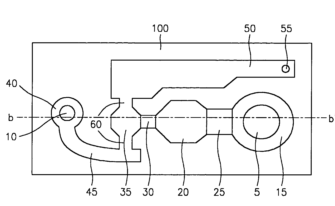
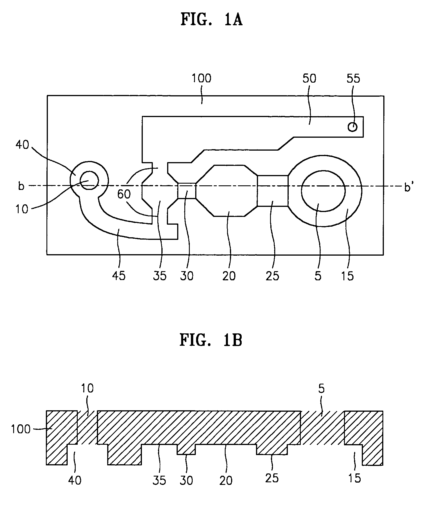
[0039]FIG. 1A is a bottom view of a channel substrate of a microfluidic device according to an embodiment of the present invention, and FIG. 1B is a sectional view taken along line b-b′ of FIG. 1A.

[0040]Referring to FIGS. 1A and 1B, holes are formed in a channel substrate 100 as a first fluid inlet port 5 and a second fluid inlet port 10. A first fluid (i.e., a fluid sample) addition chamber 15 is formed at a side of the channel substrate 100. Contiguous with the first fluid addition chamber 15, a sample reaction barrier 25, a reaction chamber 20, a time gate 30, and a sensing chamber 35 are sequentially formed. A sample injected into the first fluid inlet port 5 is flowed through the first fluid addition chamber 15, the sample reaction barrier 25, the reaction chamber 20, and the time gate 30 into the sensing chamber 35 by capillary force.

[0041]The first fluid addition chamber 15 should be large enough to accommodate the sample injected through the first fluid inlet port 5 in an am...

embodiment 2

[0048]FIG. 5 is a sectional view of a microfluidic device according to a second embodiment of the present invention. This second embodiment is similar to the first embodiment described above, with the exception of how the channel substrate 100 and the sensing substrate 200 are assembled.

[0049]The first embodiment is described as an example of applying the adhesive material 290 between the channel substrate 100 and the sensing substrate 200 to bind them together. In addition to the method of using the adhesive material 290, the channel substrate 100 and the sensing substrate 200 can be bound together by fitting projections formed on one of the substrates into grooves formed on the other.

[0050]In FIG. 5, projections 100a formed on the channel substrate 100 are fitted into the grooves 200a formed on the sensing substrate 200. When binding the channel substrate 100 and the sensing substrate 200 in this manner, an elastic polymer pad 292 may be additionally placed at contact sites of the...

embodiment 3

[0051]FIG. 6 is a plan view of a channel substrate of a microfluidic device according to a third embodiment of the present invention. This embodiment is a modification of the first embodiment for the channel substrate 100 of FIG. 1A.

[0052]Referring to FIG. 6, the reaction chamber 20 and the time gate 30 of FIG. 1A are eliminated in a channel substrate 105 so that the first fluid addition chamber 15 and the sample reaction barrier 25 are directly connected to the sensing chamber 35. Capillarity that induced natural fluid flow up to the sample reaction barrier 25 is not exerted any more when the fluid reaches the sensing chamber 35 having appreciably large outlets 60.


PUM

PropertyMeasurementUnit
contact angleaaaaaaaaaa
capillary forceaaaaaaaaaa
time delayaaaaaaaaaa

Abstract

A microfluidic device for controlling the flow of a micro amount of fluid is provided. The microfluidic device is manufactured by binding a sensing substrate including a sensing electrode, an electrode interconnect, and a electrode pad, with a channel substrate including at least two fluid inlet ports, a chamber, and a channel, wherein a first fluid injected via one of the fluid inlet ports flows by natural capillary force, and a second fluid injected via another fluid inlet port is forced to flow by an external pump. The microfluidic device controls fluid flow and flow stoppage by a combination of natural capillary flow and an externally applied pressure as a result of the action of a pump.

Description

BACKGROUND OF THE INVENTION[0001]This application claims priority from Korean Patent Application No. 2002-46794, filed on Aug. 8, 2002, in the Korean Intellectual Property Office, the disclosure of which is incorporated herein in its entirety by reference.[0002]1. Field of the Invention[0003]The present invention relates to a microfluidic device for use in a biochip, and more particularly, to a microfluidic device that controls fluid flow by using the combination of a natural capillary force and an externally applied pressure generated by pumping.[0004]2. Description of the Related Art[0005]Microfluidic devices known as the most crucial element of biochips can be implemented based on various kinetics principles. For example, a microactuating method using a micro pump and a micro valve, which are connected to a micro channel or chamber, an electrophoretic method of inducing fluid flow by applying a voltage across a micro channel, a capillary flow method using capillary force, and oth...

Claims


Application Information

Patent Timeline
Patent Type & Authority Patents(United States)
IPC IPC(8): B01L3/02G01N27/27B01L3/00
CPCB01L3/502707B01L3/50273B01L3/502746B01L2200/16B01L2300/0645B01L2300/0867Y10T436/25B01L2400/0442B01L2400/0487B01L2400/0688B01L2400/086B01L2400/088B01L2400/0406B33Y80/00G01N27/27
Inventor KO, JONG SOOYOON, HYUN CHULYANG, HAE SIKLEE, DAE-SIKCHUNG, KWANG HYOPYO, HYEON BONGKIM, SUNG JINKIM, YUN TAE
Owner ELECTRONICS & TELECOMM RES INST
Why Eureka
Try Eureka