Air compressor having changeable structure

a technology of air compressor and changeable structure, which is applied in the direction of positive displacement liquid engine, pump, machine/engine, etc., can solve the problems that the housing and the outlet tube and the ducts may not be suitably engaged in or received in some of the outer receptacles

Active Publication Date: 2007-07-10
CHOU WEN SAN
View PDF4 Cites 75 Cited by
  • Summary
  • Abstract
  • Description
  • Claims
  • Application Information

AI Technical Summary

Benefits of technology

[0011]The cover includes a check valve to control the inner air of the chamber of the cylinder housing to flow into the compartment of the outlet tube when the piston moves toward the cover, and to prevent the air from flowing out of the compartment of the outlet tube when the piston moves away from the cover.
[0012]The outlet tube includes a valve seat provided therein, and the check valve is disposed in the outlet tube and engaged with the valve seat, to control the pressurized air to flow from the chamber of the cylinder housing into the compartment of the outlet tube, and to prevent the pressurized air from flowing backwardly from the compartment of the outlet tube into the chamber of the cylinder housing.
[0013]The cover includes a valve device to control the outside air to flow into the chamber of the cylinder housing when the piston moves away from the cover, and to prevent the air from flowing out of the chamber of the cylinder housing through the valve device when the piston moves toward the cover.

Problems solved by technology

However, the outlet tube and the ducts are formed integral with the cylinder housing, such that the outlet tube and the ducts may include a large volume altogether, and may not be adjusted to different directions or positions relative to the cylinder housing, such that the cylinder housing and the outlet tube and the ducts may not be suitably engaged into or received within some of the outer receptacles or packages, or the like.

Method used


Image

  • Air compressor having changeable structure
  • Air compressor having changeable structure
  • Air compressor having changeable structure

Examples


Embodiment Construction

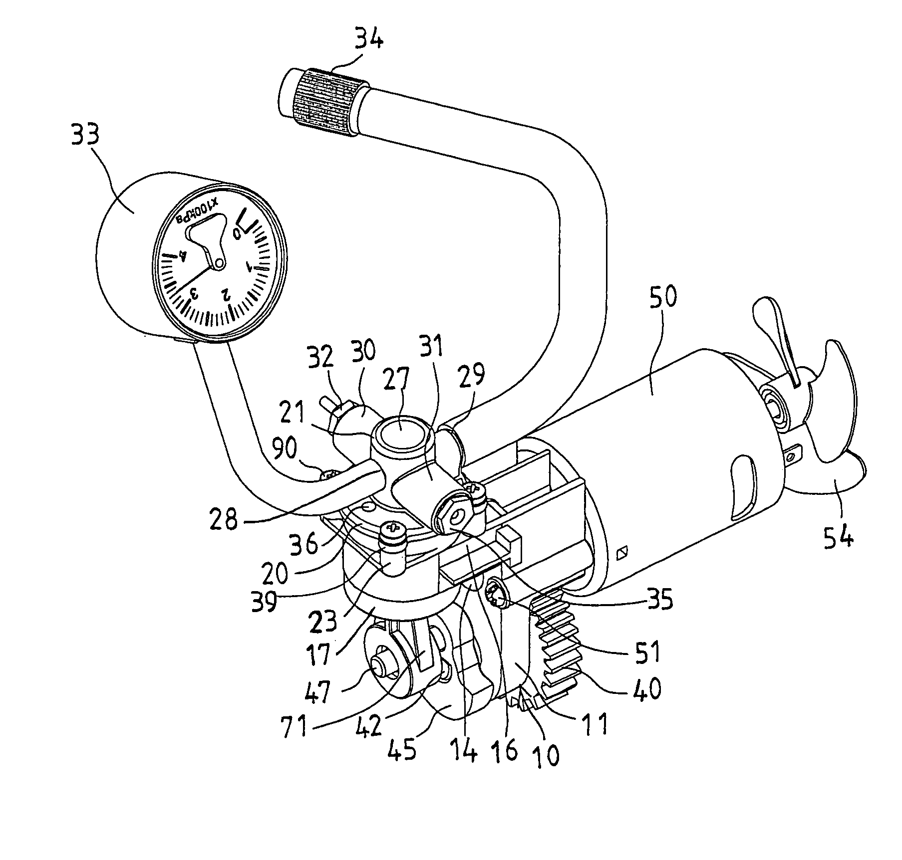
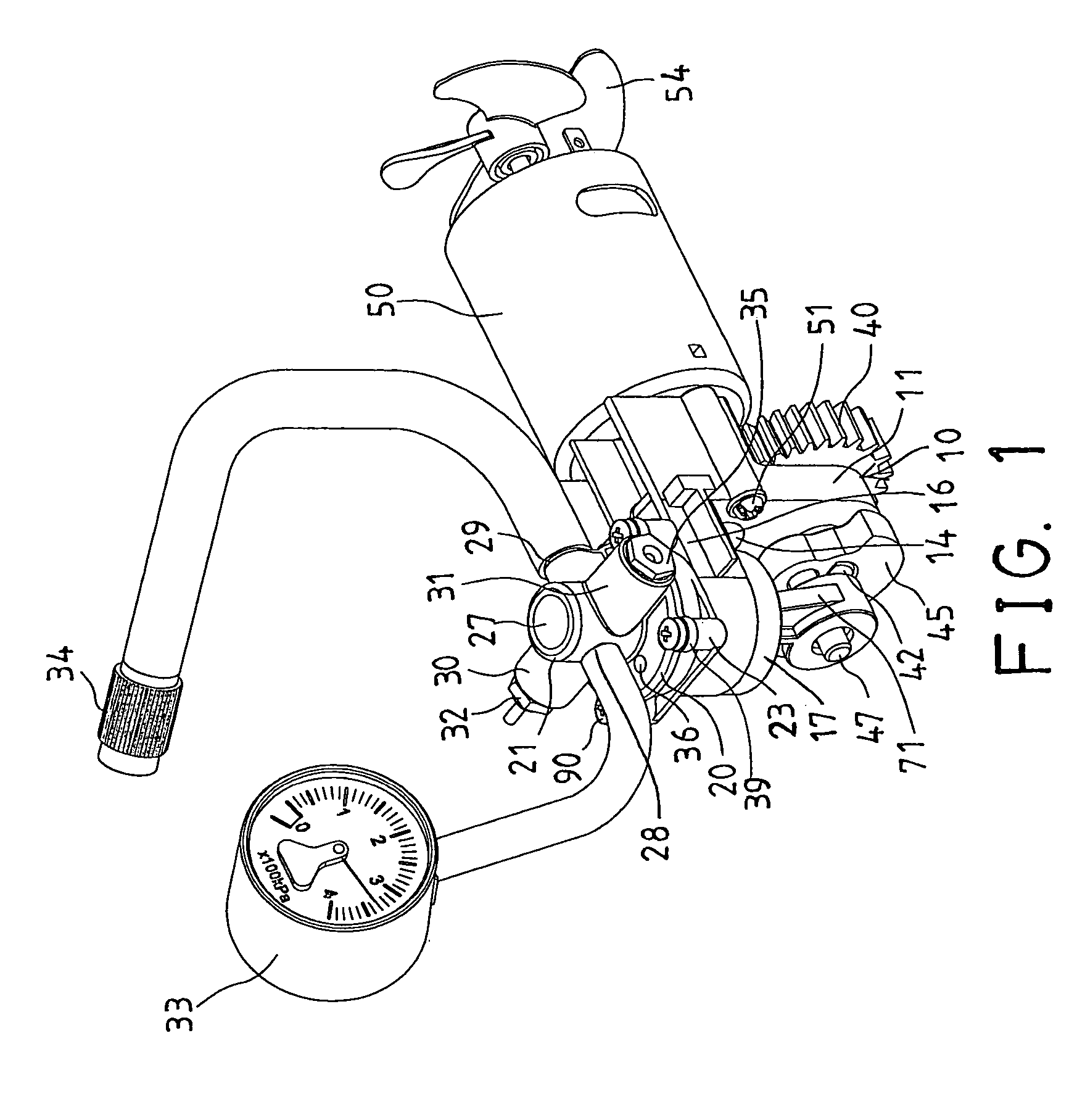
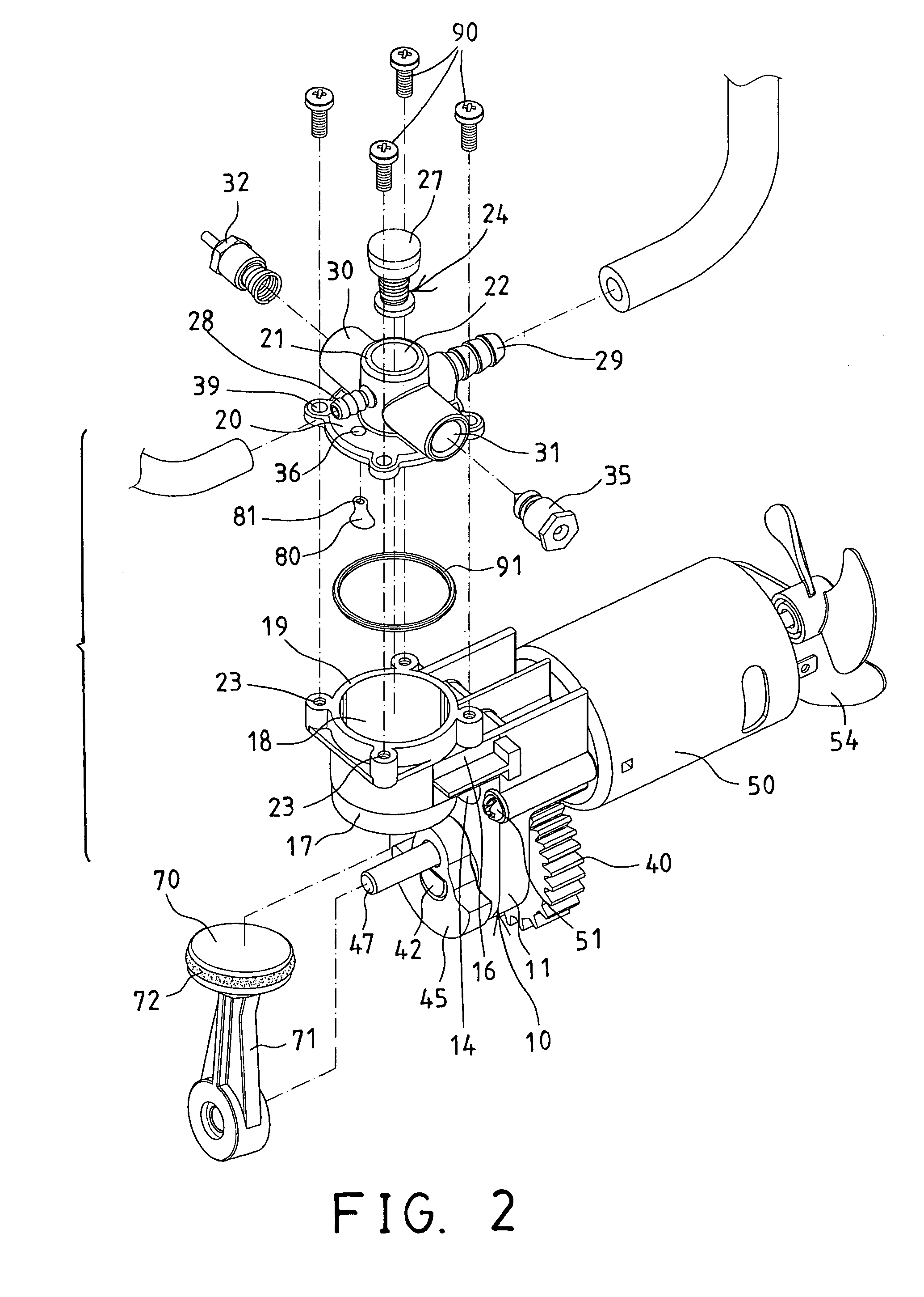
[0041]Referring to the drawings, and initially to FIGS. 1–8, an air compressor in accordance with the present invention comprises a supporting base 10 including a plate 11 having an aperture 12 formed in a lower portion 13 thereof, and having an orifice 14 formed in an upper portion 15 thereof (FIGS. 5, 8), and having an arm 16 laterally extended from the upper portion 15 thereof, and a cylinder housing 17 provided on or extended from the arm 16 and preferably formed integral with the arm 16 and the plate 11, but the cylinder housing 17 may also be separated from the plate 11 and detachably secured to the plate 11 with such as fasteners 99 (FIG. 8).

[0042]The cylinder housing 17 includes a chamber 18 formed therein (FIGS. 2–4) and having an open top (FIG. 2) and an open bottom (FIGS. 3, 4), and defined by a peripheral wall 19 (FIGS. 2), for slidably receiving a piston 70 therein. The piston 70 is slidably received in the chamber 18 of the cylinder housing 17, and includes an extensio...


PUM


Abstract

An air compressor includes a piston slidably received in a cylinder housing, and a motor coupled to the piston for moving the piston relative to the cylinder housing in a reciprocating action, in order to generate pressurized air. A cover is detachably secured on top of the cylinder housing, and includes an outlet tube having a compartment communicating with the cylinder housing, for receiving pressurized air from the cylinder housing, and includes an inlet blocked by a check valve device. The cover may be adjusted and secured to the cylinder housing, to adjust the inlet to different position relative to the cylinder housing, and to prevent the inlet from being blocked by objects.

Description

BACKGROUND OF THE INVENTION[0001]1. Field of the Invention[0002]The present invention relates to an air compressor, and more particularly to an air compressor having a detachable or changeable structure for allowing an outlet tube of the air compressor to be adjusted to different angular positions or directions, and for allowing the air compressor to be attached to or received within various receptacles.[0003]2. Description of the Prior Art[0004]Typical air compressors comprise a cylinder housing attached or secured to a base and having a piston slidably disposed therein, and a motor secured to the base and coupled to the piston of the cylinder housing for actuating or driving the piston of the cylinder housing in a reciprocating action.[0005]The applicant has developed various kinds of typical air compressors, such as U.S. Pat. No. 6,846,162 to Chou, which also comprises a piston slidably disposed within a cylinder housing and slidable along or relative to the cylinder housing in a...

Claims


Application Information

Patent Timeline
Patent Type & Authority Patents(United States)
IPC IPC(8): F01P1/04
CPCF04B35/04F04B39/123
Inventor CHOU, WEN SAN
Owner CHOU WEN SAN
Why Eureka
Try Eureka