Coupling structure of shaft body and shaft joint

a technology of coupling structure and shaft body, which is applied in the direction of couplings, hose connections, transportation and packaging, etc., can solve the problems of poor workability, high cost, and insufficient and achieve the effect of increasing the fastening strength of the plate body in a simple manner

Active Publication Date: 2007-07-10
JTEKT CORP
View PDF14 Cites 4 Cited by
  • Summary
  • Abstract
  • Description
  • Claims
  • Application Information

AI Technical Summary

Benefits of technology

[0009]The present invention has been made with the aim of solving the above problems, and it is an object of the present invention to provide a coupling structure of a shaft body and a shaft joint, capable of increasing the fastening strength of the plate body in a simple manner without employing a special fastening technique.
[0011]With this coupling structure whereby the projection projecting from the supported portion of the plate body can be fitted into the recessed portion of the shaft joint body and / or the locking body by press-fitting the locking body into the bore of the shaft joint body, it is possible to prevent trembling of the plate body and to increase the fastening strength of the plate body.
[0013]With this coupling structure whereby it is possible to cause the projection projecting from the supported portion of the plate body to cut into the shaft joint body and / or the locking body by press-fitting the locking body into the bore of the shaft joint body, trembling of the plate body can be prevented without forming a recessed portion in advance.

Problems solved by technology

In the coupling structure constructed as described above, however, since the plate body is fastened to the shaft joint by supporting the flat supported portion, the fastening strength of the plate body is not sufficient and the plate body trembles.
However, since both of these techniques are special fastening techniques, there arise problems of poor workability and high costs.

Method used


Image

  • Coupling structure of shaft body and shaft joint
  • Coupling structure of shaft body and shaft joint
  • Coupling structure of shaft body and shaft joint

Examples


Embodiment Construction

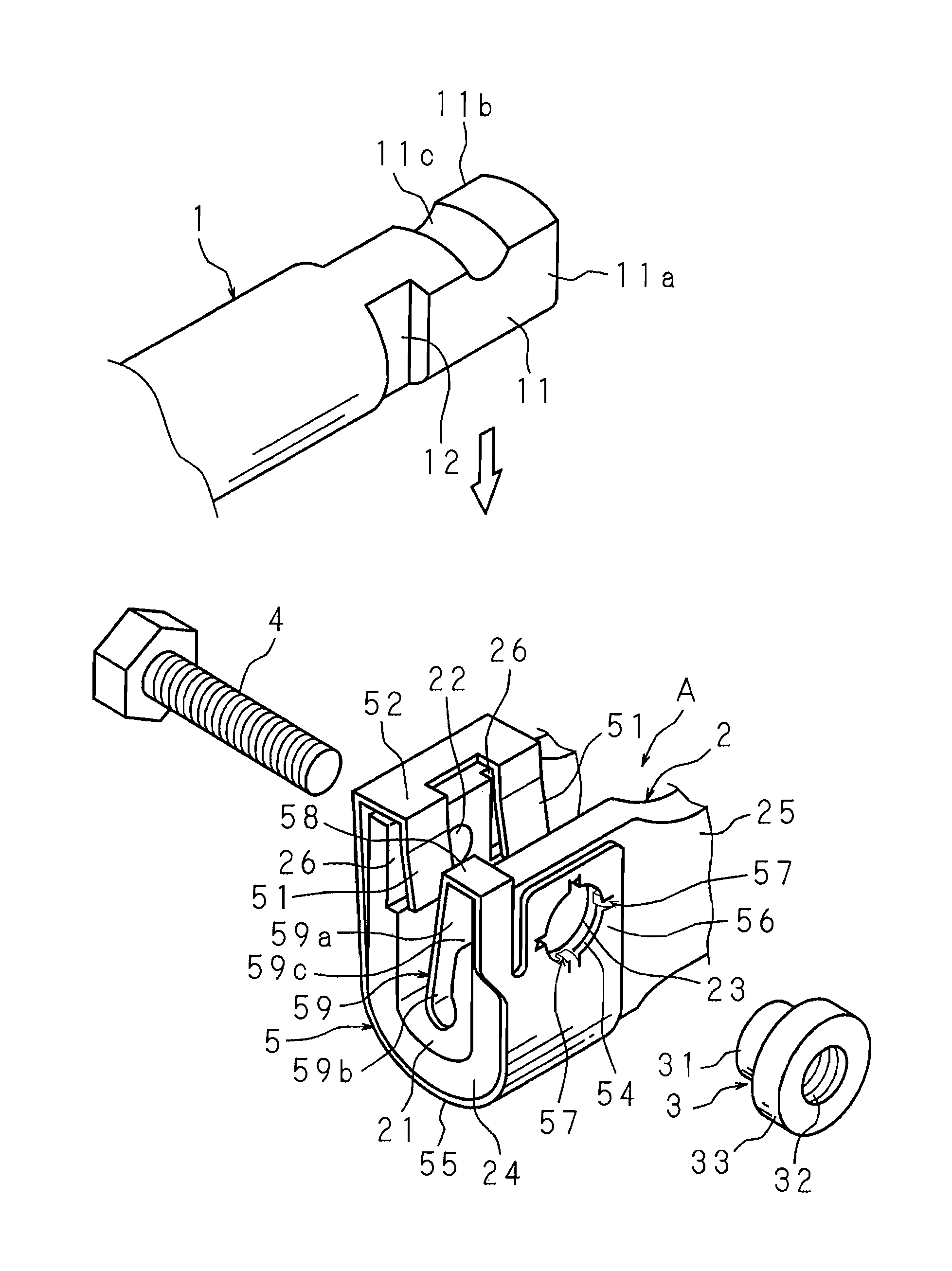
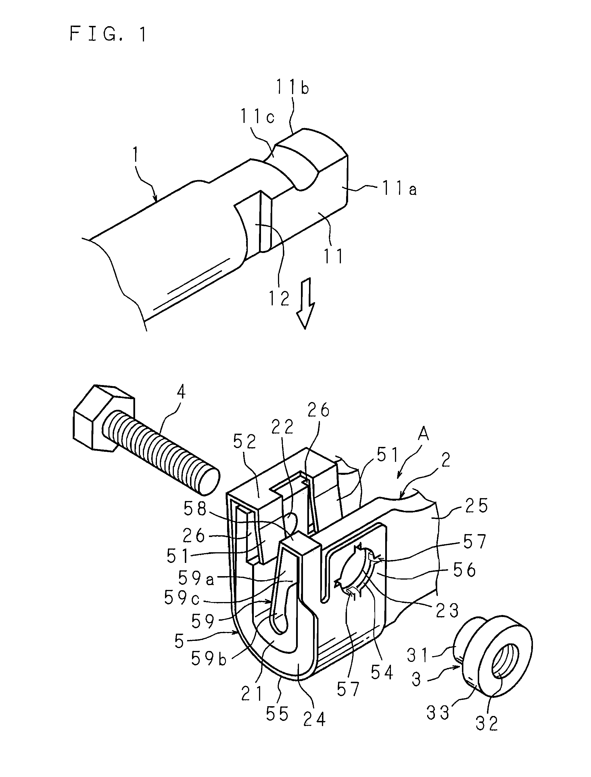
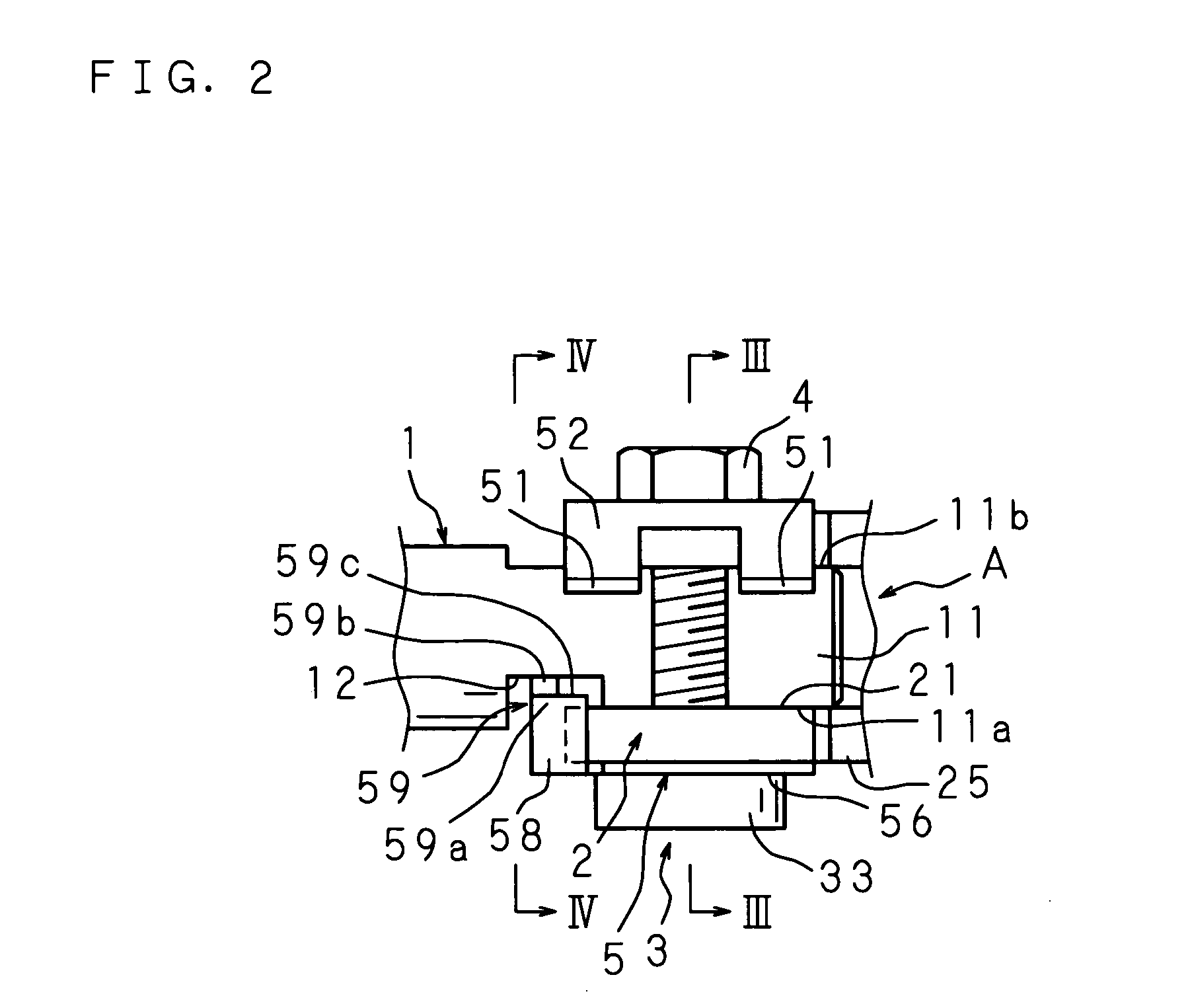
[0023]The following description will explain the present invention in detail, based on the drawings illustrating an embodiment thereof. FIG. 1 is an exploded perspective view of a coupling structure according to the present invention. FIG. 2 is a plan view. FIG. 3 is a cross sectional view along the III—III line in FIG. 2. FIG. 4 is a cross sectional view along the IV—IV line in FIG. 2.

[0024]This coupling structure is for coupling a shaft body 1 having a non-circular engagement portion 11 on one end thereof with a shaft joint A, which comprises an engagement groove 21 with which the engagement portion 11 is engaged so that relative rotation is impossible, a shaft joint body 2 with two bores 22 and 23 facing the engagement groove 21 and a locking body 3 press-fitted into a bore 23, with a coupling shaft 4 inserted into the bores 22 and 23 and locked with the locking body 3. The coupling structure includes a plate body 5 supported between the locking body 3 and the shaft joint body 2....


PUM


Abstract

The coupling structure includes: a shaft body 1 having an engagement portion 11 with a slip-off preventing groove; a shaft joint body 2 having an engagement groove 21 with which the engagement portion 11 is engaged and bores 22 and 23 facing the engagement groove 21; a locking body 3 press-fitted into the bore 23; and a plate body 5 having regulating tongues 51 for regulating movement of the shaft body 1, a supported portion 56 extending from the regulating tongues 51 and supported between the locking body 3 and the shaft joint body 2, and a projection 57 projecting from the supported portion 56. The shaft joint body 2 and / or the locking body 3 have a recessed portion 27 into which the projection 57 is fitted.

Description

BACKGROUND OF THE INVENTION[0001]1. Field of the Invention[0002]The present invention relates to a coupling structure of a shaft body and a shaft joint.[0003]2. Description of Related Art[0004]A steering apparatus for a vehicle comprises: a steering shaft with one end connected to a steering wheel; a transmission shaft having, on one end thereof, a shaft joint connected to the other end of the steering shaft; and a pinion shaft coupled to the other end of the transmission shaft through the shaft joint and having a pinion meshing with the mid portion of a rack shaft which extends in the left and right direction of the vehicle.[0005]The coupling structure of a shaft joint and a shaft body composed of a steering shaft or a pinion shaft is disclosed, for example, in Japanese Patent Application Laid-Open No. 2000-310232.[0006]According to the coupling structure of Japanese Patent Application Laid-Open No. 2000-310232, an end of the shaft body has a non-circular engagement portion having ...

Claims


Application Information

Patent Timeline
Patent Type & Authority Patents(United States)
IPC IPC(8): F16D1/08B62D1/20F16B2/24F16D1/06F16D3/26F16D3/38
CPCF16D1/0864F16D3/387Y10T403/1608Y10T403/32901Y10T403/32041F16D1/116
Inventor AOTA, KENICHIKINME, SHIGETAKA
Owner JTEKT CORP
Why Eureka
Try Eureka