
Electronic instrument system with multiple-configuration instrument modules

a technology of instrument modules and electronic instruments, applied in the direction of electrical apparatus casings/cabinets/drawers, support structure mounting, rack/frame construction, etc., can solve the problems of wasting the purchase of stand-alone measurement devices, the cost of the system, and the lack of measurement modules

Inactive Publication Date: 2007-07-10
AGILENT TECH INC
View PDF7 Cites 69 Cited by
  • Summary
  • Abstract
  • Description
  • Claims
  • Application Information

AI Technical Summary

Benefits of technology

[0010]More particularly, an electronic instrument system has first and second mutually-exclusive modes of operation. The system includes an instrument module having first and second communications channels, each for linking the instrument module to one or more processors. The first communications channel comprises a first connector attached to the instrument module for mating to a backplane connector electrically connect

Problems solved by technology

The problem is that the cost of the system, even without any measurement modules, is already around US$3000 (all prices are in year 2006 dollars), and after adding measurement modules can be well over US$5000.
However, if they later need to perform more complicated DAQ, measurement, or control applications, the purchase of the stand-alone measurement devices will have been a waste and they will need to start from scratch by purchasing a new high-priced chassis and several new high-priced chassis-based measurement devices.

Method used


Image

  • Electronic instrument system with multiple-configuration instrument modules
  • Electronic instrument system with multiple-configuration instrument modules
  • Electronic instrument system with multiple-configuration instrument modules

Examples


Embodiment Construction

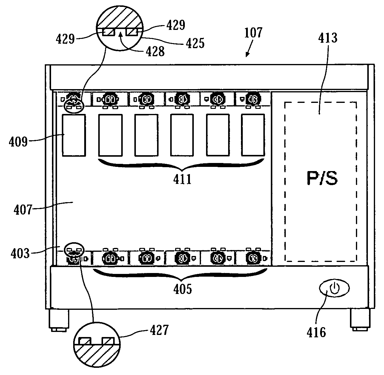
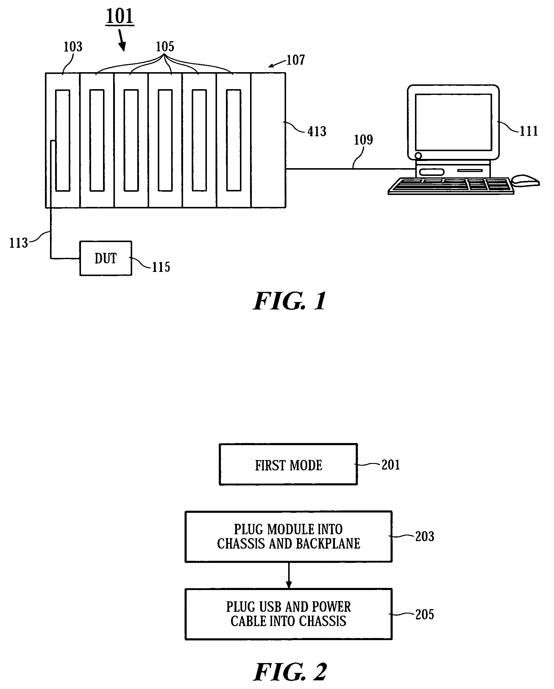
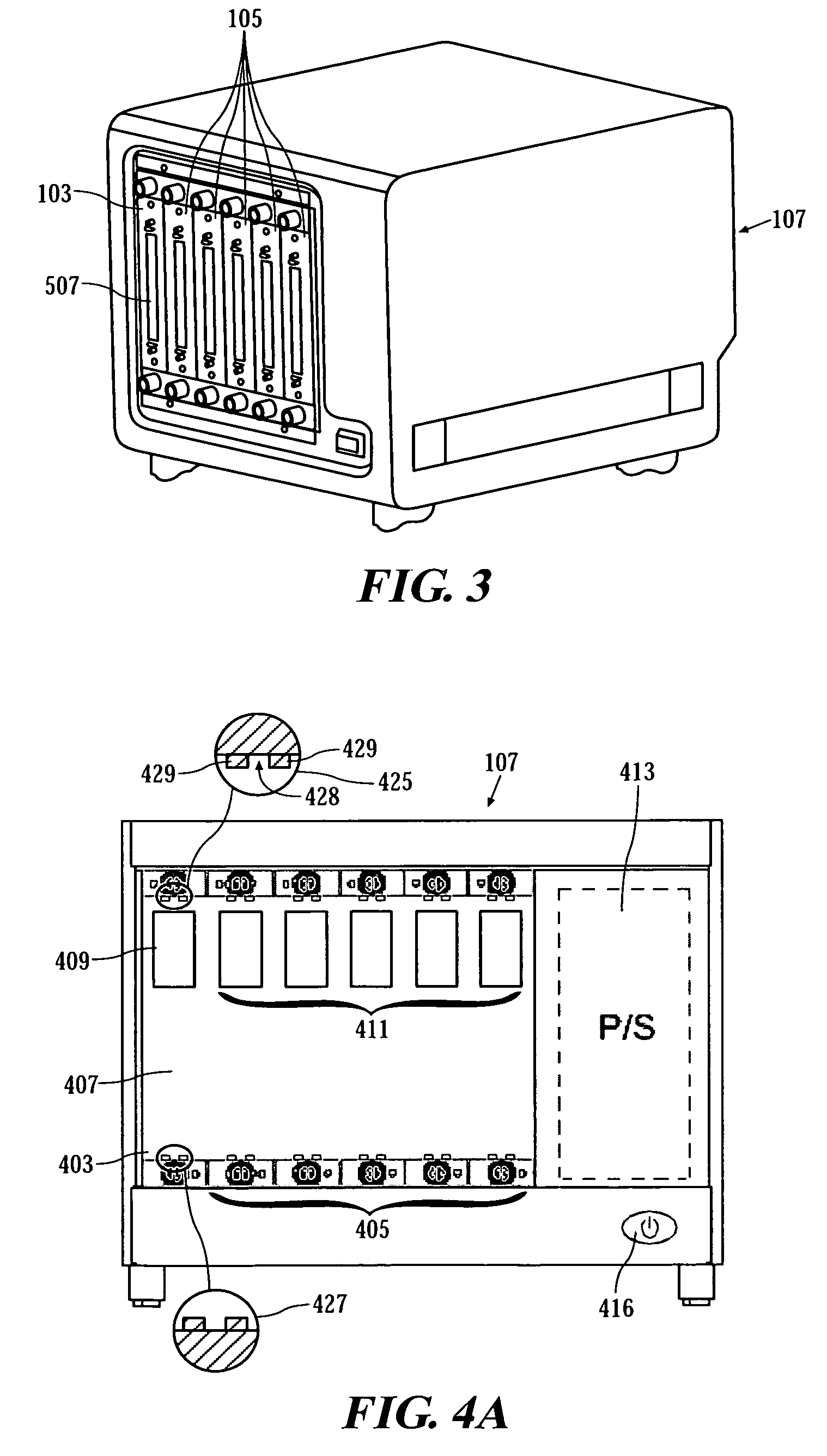
[0031]FIG. 2 is a flowchart showing the steps for a first mode of operation 201 of the present invention. FIG. 1 shows an electronic instrument system 101 configured for the first mode of operation 201. In the first mode of operation 201 an instrument module 103 and additional instrument modules 105 are plugged into a card-cage or chassis 107. The instrument module 103 and additional instrument modules 105 are plugged into the chassis 107 at the Step 203 of FIG. 2. A first communications channel 109 is provided for linking the instrument module 103 and additional instrument modules 105 to each other and to one or more processors, for example the PC 111. When the electronic instrument system 101 operates in the first mode it communicates through the first communications channel 109. A third communications channel 113 links the instrument module 103, or any of the additional instrument modules 105, with an external device-under-test (DUT) 115 undergoing test or measurement by the elec...


PUM


Abstract

An electronic instrument system uses a “DualPlay” concept comprising first and second mutually-exclusive modes of operation. The system includes an instrument module having first and second communications channels, each for linking the instrument module to one or more processors. The first communications channel comprises a first connector attached to the instrument module for mating to a backplane connector electrically connected to traces. The system operates in the first mode when the instrument module communicates through the first communications channel. Additionally, the system operates in the second mode when the instrument module communicates through the second communications channel, the first connector is disengaged from the backplane connector and the electronic instrument is not communicating through the first communications channel.

Description

FIELD OF THE INVENTION[0001]The invention relates to the field of electronic test instruments.BACKGROUND OF THE INVENTION[0002]U.S. Pat. No. 6,823,283 to Steger, et al., describes a measurement device. The measurement device is comprised of one or more measurement modules or cards inserted into a carrier unit. The carrier unit is a “chassis” or “card carrier” such as the NATIONAL INSTRUMENTS (“NI”) PXI-1031 PXI Chassis. The measurement modules are sometimes data acquisition (“DAQ”) modules such as the NI PXI-4220 module, or other modules such as digitizers, digital multimeters, scopes, or arbitrary waveform generators.[0003]The chassis can also include a NI PXI-8184 Celeron-Based Embedded Controller for controlling the measurement modules. Alternatively, an external personal computer (“PC”) can be used to control the modules.[0004]Included in the chassis is a backplane providing electrical communication with the measurement modules. The chassis can be a PXI standard chassis and the ...

Claims


Application Information

Patent Timeline
IPC IPC(8): H05K5/00
CPCG01R31/2834
Inventor YEAP, BOON LEONGFOO, SHIEW FOELIM, CHEO BONGTAY, ENG SU
Owner AGILENT TECH INC
Learn More