Expander device

a technology of extruder and rotor, which is applied in the direction of fluid removal, earthwork drilling and mining, and wellbore/well accessories, etc., can solve the problems of inability to complete the expansion process, difficulty in fishing operations, and stuck, and achieve the effect of overturning the biasing for

Inactive Publication Date: 2007-07-17
WEATHERFORD TECH HLDG LLC
View PDF22 Cites 28 Cited by
  • Summary
  • Abstract
  • Description
  • Claims
  • Application Information

AI Technical Summary

Benefits of technology

[0037]The or each radially moveable portion typically comprises one or more fingers. The or each finger is typically coupled to the body so that they can move in a radial and/or axial direction. Thus, the or each finger can expand or contract to adjust an outer diameter of the apparatus. Typically, the or each finger is held in a radially expanded position by the fluid in the fluid chamber or the inflatable element. In

Problems solved by technology

As the expander device (e.g. a cone) is pushed or pulled through the expandable member, it can become stuck due to, for example, immovable portions of the inner wall of the uncased borehole that protrude inwards into the path of the expander device.
In such a case, the travel of the expander device may be restricted by the inward protrusion, and as a result, the expansion process cannot be completed, as the device becomes stuck at the

Method used


Image

  • Expander device
  • Expander device
  • Expander device

Examples


Embodiment Construction

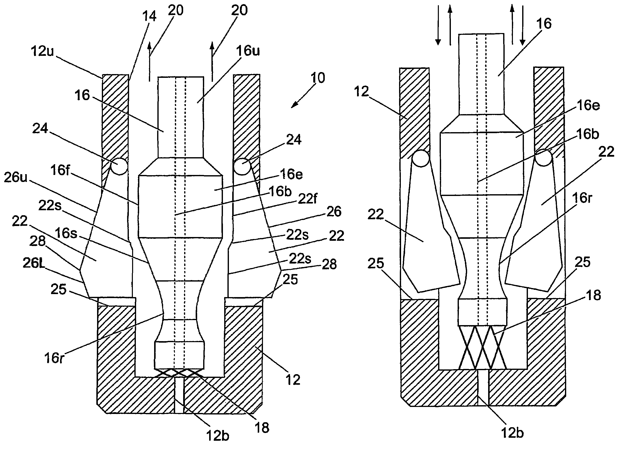
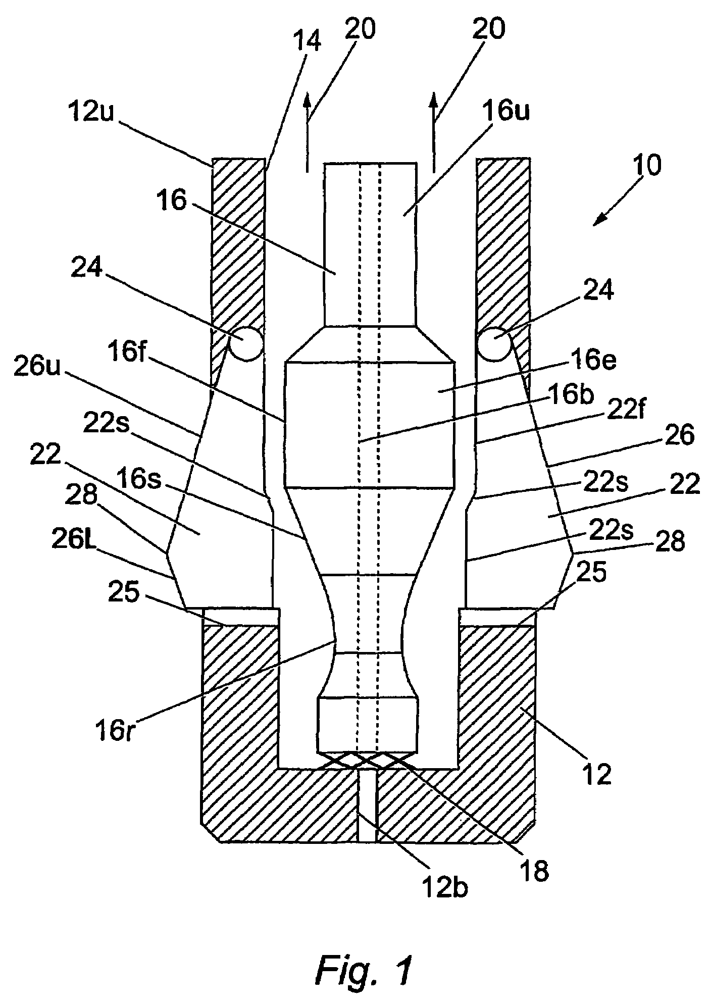
[0054]Referring to the drawings, FIG. 1 shows a part cross-sectional elevation of an exemplary embodiment of apparatus, generally designated 10, for expanding an expandable member such as liners, casings, drill pipe and other such downhole tubulars. It should be noted that the terms “upper” and “lower” will be used herein with reference to the orientation of the apparatus 10 as shown in FIG. 1, but this is arbitrary.

[0055]The expandable member may comprise any tubular, such as drill pipe, liner, casing or the like and is typically of a ductile material so that it can be radially expanded. The radial expansion of the expandable member typically causes the member to undergo plastic and / or elastic deformation to increase its inner and outer diameters.

[0056]Apparatus 10 includes a housing 12 that is typically cylindrical, although other shapes and configurations are also contemplated. Housing 12 is provided with a blind bore 14.

[0057]A shaft 16 is located within the bore 14 and is attac...


PUM


Abstract

Apparatus (9) for radially expanding an expandable member, the apparatus including a plurality of radially moveable fingers (22). The radially moveable fingers (22) can move between two positions; in a first position, the moveable fingers (22) are radially extended to a form a cone to facilitate radial expansion of the expandable member; in the second position, one or more of the radially movable fingers (22) can move radially inward so that restrictions in the path of the apparatus can be by-passed.

Description

CROSS-REFERENCE TO RELATED APPLICATIONS[0001]This application claims benefit of PCT International application number PCT / GB02 / 00356 filed on Jan. 28, 2002, entitled “Expander Device”, which claims benefit of British application serial number 0102021.3, filed on Jan. 26, 2001.[0002]The present invention relates to apparatus that is particularly suited for radially expanding expandable members, such as liners, casings, tubulars and the like.[0003]The present invention relates to apparatus that is particularly suited for radially expanding expandable members, such as liners, casings, tubulars and the like.DESCRIPTION OF THE RELATED ART[0004]It is known to use an expander device to expand at least a portion of an expandable member. Expandable members are typically of a ductile material so that they can undergo plastic and / or elastic deformation using an expander device. Expandable members can include liner, casing, drill pipe and other tubulars. Use of the term “expandable member” herei...

Claims


Application Information

Patent Timeline
IPC IPC(8): E21B29/10E21B23/04E21B43/10
CPCE21B43/105
Inventor OOSTERLING, PETERMACKENZIE, ALAN
Owner WEATHERFORD TECH HLDG LLC
Why Eureka
Try Eureka