Permanent magnet electric machine having reduced cogging torque

a permanent magnet electric machine and torque reduction technology, which is applied in the direction of dynamo-electric machines, synchronous machines with stationary armatures, electrical apparatus, etc., can solve the problems of vibration and noise within the permanent magnet electric machine, adversely affecting machine performance, and additional nois

Inactive Publication Date: 2007-07-17
NIDEC MOTOR CORP
View PDF21 Cites 30 Cited by
  • Summary
  • Abstract
  • Description
  • Claims
  • Application Information

AI Technical Summary

Benefits of technology

[0007]According to other features of the invention, the permanent magnet electric machine has a 12 / 10 slot / pole combination. The permanent magnets have a magnet dimension angle that is between 31 and 35 degrees. If two axial rotor sections are employed, they are rotationally offset by 3 degrees. If additional axial rotor sections are employed, the offset angle for all of the axial rotor sections is equal to the cogging angle divided by the number of axial rotor sections. An air gap ratio of the electric machine is between 1.35 and 2.5. A slot opening ratio of the electric machine is less than or equal to one.
[0008]According to other features of the invention, the permanent magnet electric machine has an 18 / 12 slot / pole combination. The permanent magnets have a magnet dimension angle that is between 25 and 28 degrees. If two axial rotor sections are employed, they are rotationally offset by 5 degrees. If additional axial rotor sections are employed, the offset angle for all of the axial rotor sections is equal to the cogging angle divided by the number of axial rotor sections. An air gap ratio of the electric machine is between 1.35 and 2.5. A slot opening ratio of the electric machine is less than or equal to one.

Problems solved by technology

Electric machines with permanent magnet rotors often have cogging torque that adversely impacts machine performance.
The torque oscillations cause vibration and noise within the permanent magnet electric machine.
The variation in torque can also cause vibration in the equipment that is driven by the machine, which causes additional noise.
Skewing the permanent magnets increases material and manufacturing costs due to the complex and non-uniform shape of the permanent magnets.
The non-uniform permanent magnets are also difficult to assemble.

Method used


Image

  • Permanent magnet electric machine having reduced cogging torque
  • Permanent magnet electric machine having reduced cogging torque
  • Permanent magnet electric machine having reduced cogging torque

Examples


Embodiment Construction

[0017]The ensuing detailed description provides preferred exemplary embodiments only and is not intended to limit the scope, applicability or configuration of the present invention. Rather, the ensuing detailed description of the preferred exemplary embodiments will provide those skilled in the art with an enabling description for implementing the preferred exemplary embodiments of the present invention. It being understood that various changes may be made in the function and arrangement of the elements without departing from the spirit and scope of the invention as set forth in the appended claims.

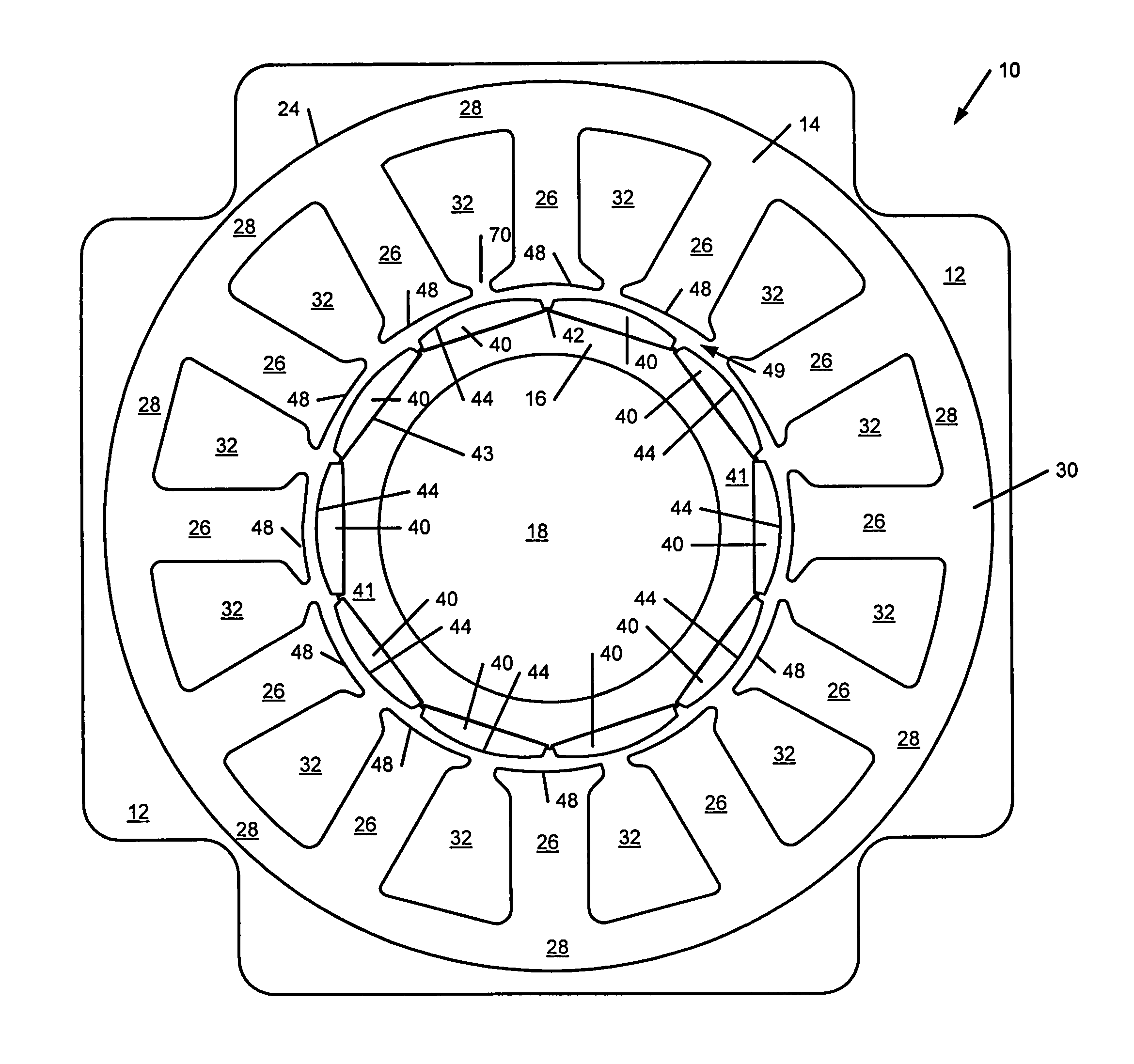
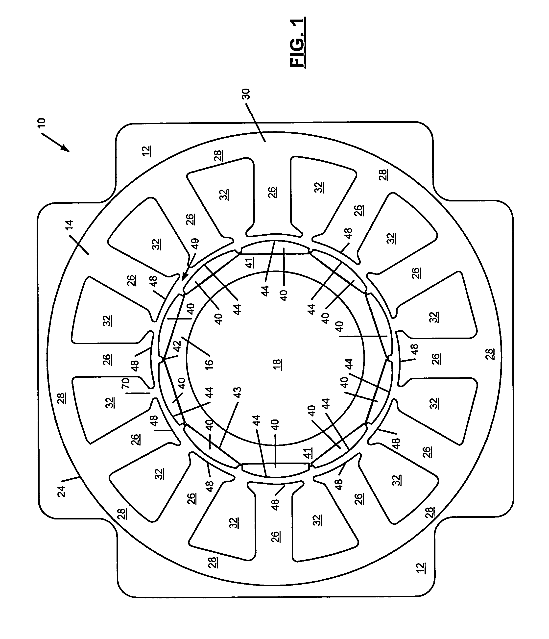
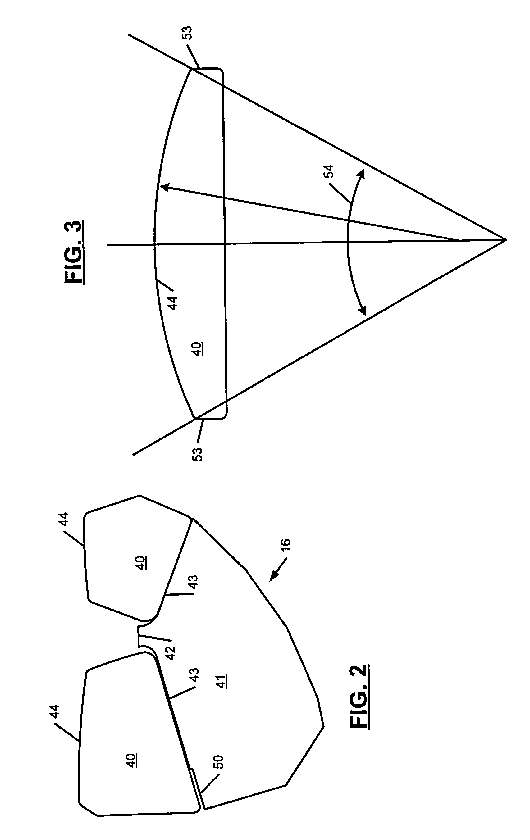
[0018]The permanent magnet electric machine according to the invention dramatically reduces cogging torque by providing a rotor with two or more axial rotor sections. The axial rotor sections are rotationally offset by an offset angle that is equal to the cogging angle divided by the number of axial rotor sections. The axial rotor sections have optimized dimensions that produce symmetric,...


PUM


Abstract

A permanent magnet electric machine includes a stator with salient stator poles. A rotor includes two or more axial rotor sections that are rotationally offset by an offset angle equal to the cogging angle divided by the number of axial rotor sections. The axial rotor sections include rotor poles with permanent magnets. In one embodiment, the permanent magnet electric machine has a 12/10 slot/pole combination. The permanent magnets have a magnet dimension angle between 31 and 35 degrees. An air gap ratio of the electric machine is between 1.35 and 2.5. A slot opening ratio of the electric machine is less than or equal to one. In another embodiment, the permanent magnet electric machine has an 18/12 slot/pole combination. The permanent magnets have a magnet dimension angle that is between 25 and 28 degrees. An air gap ratio of the electric machine is between 1.35 and 2.5. A slot opening ratio of the electric machine is less than or equal to one.

Description

FIELD OF THE INVENTION[0001]This invention relates to permanent magnet electric machines, and more particularly to permanent magnet electric machines having reduced cogging torque.BACKGROUND OF THE INVENTION[0002]Permanent magnet electric machines, such as motors and generators, include a stationary stator that defines salient poles and inter-pole slots that are located between the salient poles. The stator is often mounted on an inner surface of a machine housing with the salient poles projecting radially inwardly. The permanent magnet electric machines also include a rotor that is mounted on a shaft, that includes rotor poles and that rotates on the shaft relative to the stator. The rotor poles include permanent magnets that are attached to a radially outer surface of the rotor. Winding wire is wound around the stator poles in the stator slots. A circuit board or another connection device couples the stator pole windings to a drive circuit. The drive circuit generates a set of sta...

Claims


Application Information

Patent Timeline
Patent Type & Authority Patents(United States)
IPC IPC(8): H02K21/12H02K29/03
CPCH02K29/03
Inventor WALLS, TODD A.CRAPO, ALAN D.
Owner NIDEC MOTOR CORP
Why Eureka
Try Eureka