Coordinated regenerative and engine retard braking for a hybrid vehicle

a hybrid vehicle and regenerative braking technology, applied in the direction of electrical control, process and machine control, etc., can solve the problems and affecting the efficiency of regenerative braking. the effect of reducing the contribution of regenerative braking

Active Publication Date: 2005-11-17
ALLISON TRANSMISSION INC
View PDF10 Cites 187 Cited by
  • Summary
  • Abstract
  • Description
  • Claims
  • Application Information

AI Technical Summary

Benefits of technology

[0009] A vehicle includes a hybrid powertrain having a retarded diesel engine, such as by an exhaust brake or an engine compression brake, and at least one electric machine and a battery pack. The diesel engine and electric machine are operatively coupled to a driveline having an output in accordance with known speed relationships between the diesel engine, the electric machine and output, wherein the output power is substantially equivalent to the summation of engine power and the electric machine power. In accordance with the invention, coordination of regenerative braking and engine retard braking of a vehicle includes providing a vehicle braking request, such as by interpreted operator brake pedal effort. A first braking contribution to the output is provided by the electric machine, and a second braking contribution to the output is provided by the retarded engine. Engine speed is controlled higher when power flow to the energy storage system exceeds a predetermined power limit. This effectively increases the engine retard braking contribution and decreases the regenerative braking contribution in order to meet a given driver braking request. Engine speed is controlled lower when power flow to the battery pack does not exceed the predetermined power limit. This effectively decreases the engine retard braking contribution and increases the regenerative braking contribution. Vehicle braking contribution priority is first to said at least one electric machine and second to said retarded engine. Where battery power limits are not tight and power flow into the battery pack is acceptable, the engine speed may be determined in accordance with one of a battery difference which is a measured difference between actual battery power and a predetermined limit, and an output difference which is a measure of the difference between the output torque requested and the output torque commanded. Where battery power limits are tight, the engine speed may be determined solely in accordance with the output difference. Insignificant output difference results in engine speed setting in accordance with a predetermined calibration rate whereas significant output difference results in engine speed setting determined in accordance with the output difference.

Problems solved by technology

However, even under ideal conditions, the substantial power flows represented by decelerating a massive vehicle may not be able to be accommodated by the energy storage system.
Attempting to return too much energy, or returning energy at power flows in excess of the reasonable capacity of the energy storage system to accept same, may result in irreparable harm to the energy storage system.
Therefore, even with conservative calibrations, a regenerative braking system may not provide optimum energy return and power flow to the energy storage system in accordance with other desirable objectives.
However, engine retard braking has conventionally been employed in a substantially uncontrolled fashion at the request of the vehicle driver in accordance with actuation of the engine braking or exhaust braking mechanism and gear ratio selection.
In a hybrid powertrain equipped vehicle, such non-ideal application of engine retard braking may supplant the need for regenerative braking and forgo the significant efficiency gains that might otherwise be effected by returning the dissipated engine retarding energy to the energy storage system.
Furthermore, such non-ideal and unpredictable application of engine retard braking frustrates the objective of returning regenerative braking energy in a controlled fashion to the energy storage system.

Method used


Image

  • Coordinated regenerative and engine retard braking for a hybrid vehicle
  • Coordinated regenerative and engine retard braking for a hybrid vehicle
  • Coordinated regenerative and engine retard braking for a hybrid vehicle

Examples


Embodiment Construction

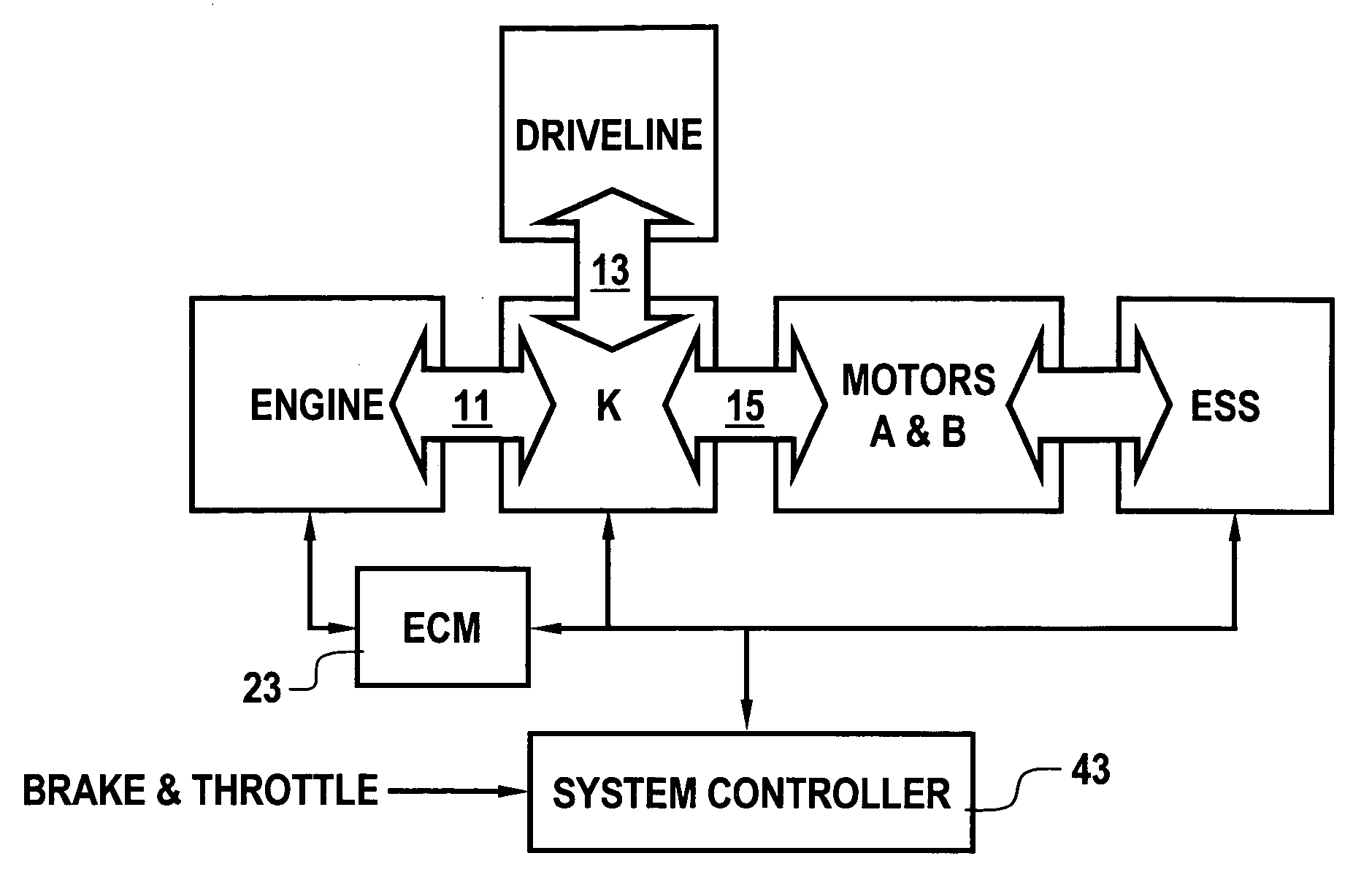
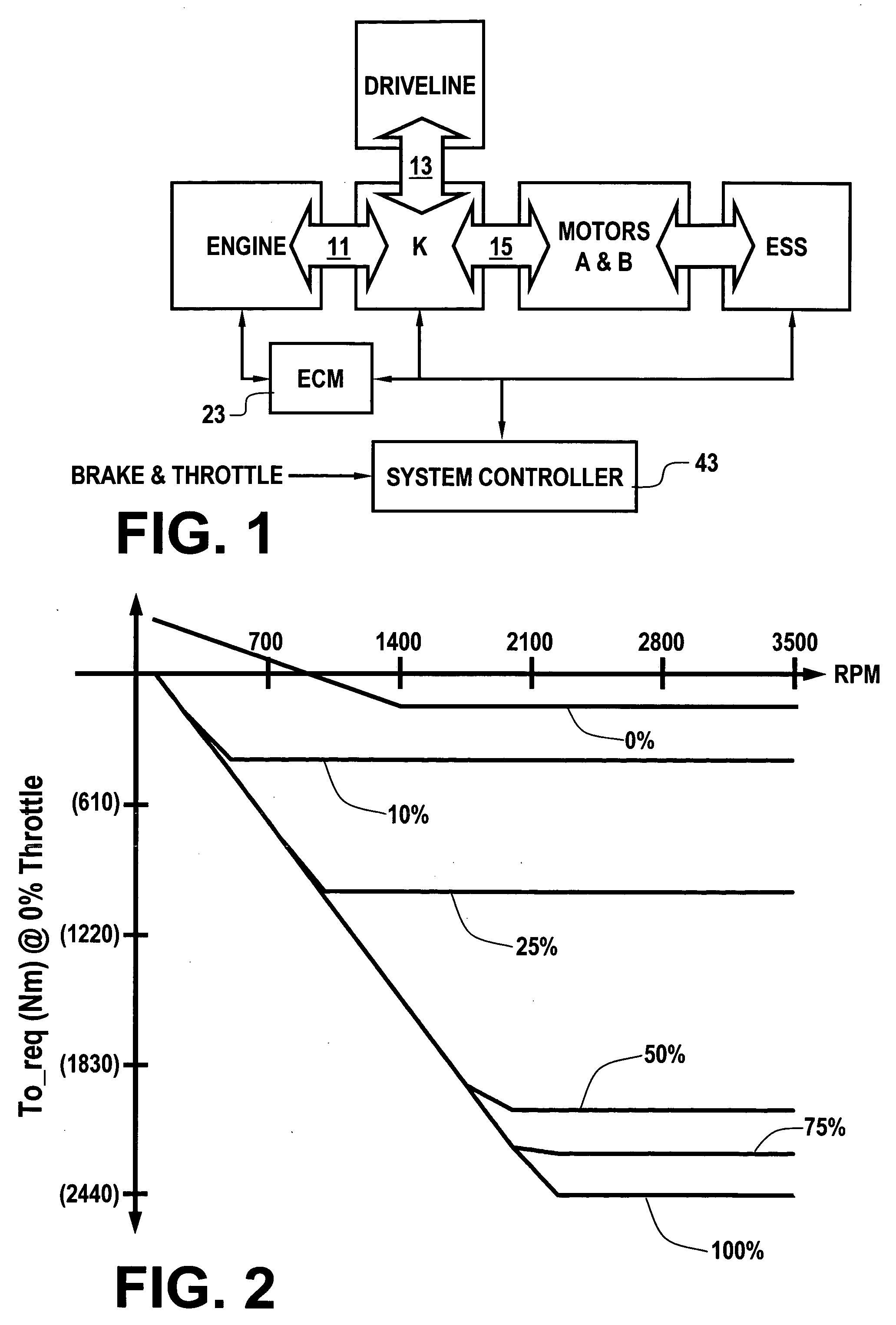
[0016] With reference first to FIG. 1, a block diagram of an exemplary hybrid powertrain to which the present coordinated control of electrically regenerative and engine retard braking is applicable is illustrated. A hybrid powertrain includes a diesel compression ignition engine, a vehicle driveline and one or more electric motors (hereafter motor) operatively coupled to one another, for example, through a coupling means (K) comprising one or more planetary gearsets and selective coupling paths in accordance with application and release of various torque transfer devices. The engine is coupled to the coupling means at a mechanical input thereof (11). The driveline is coupled to the coupling means at a mechanical output thereof (13). The motor is coupled to the coupling means at an input thereof (15). Neglecting power losses, the power flows between the engine, driveline and motor balance. And, the power at the driveline is equivalent to the summation of the powers at the engine and...


PUM


Abstract

A hybrid vehicle includes a powertrain having a retarded diesel engine, an electric machine and energy storage system. The engine and motor are operatively coupled through one or more planetary gearsets and selective coupling paths in accordance with application and release of various torque transfer devices to a drivetrain via an output. Regenerative and retarded engine braking are coordinated to provide priority to energy return to an energy storage system in accordance with predetermined power flow limits. Power flow in excess of the limits are handled by increased engine retard braking contributions via engine speed increases.

Description

CROSS-REFERENCE TO RELATED APPLICATIONS [0001] This application is related to co-pending and commonly assigned U.S. Ser. No. 10 / ______ (Attorney Docket No. GP-304459) entitled “ENGINE RETARD OPERATION SCHEDULING AND MANAGEMENT IN A HYBRID VEHICLE” filed on even date herewith and incorporated herein by reference.TECHNICAL FIELD [0002] The present invention is related to hybrid vehicular powertrains. More particularly, the present invention is concerned with vehicle braking management in such powertrains. BACKGROUND OF THE INVENTION [0003] Various hybrid powertrain architectures are known for managing the input and output torques of various prime-movers in hybrid vehicles, most commonly internal combustion engines and electric machines. Series hybrid architectures are generally characterized by an internal combustion engine driving an electric generator which in turn provides electrical power to an electric drivetrain and to a battery pack. The internal combustion engine in a series h...

Claims


Application Information

Patent Timeline
Patent Type & Authority Applications(United States)
IPC IPC(8): B60T1/10B60W10/06B60W10/10B60W20/00F02D9/06F02D13/04F02D41/12G06F17/00
CPCB60T1/10B60W10/06B60W10/10B60W10/196Y10T477/24B60W2710/0644F02D9/06F02D13/04F02D41/12B60W20/102B60W20/11
Inventor TAO, XUEFENG T.HUBBARD, GREGORY A.HSIEH, TUNG-MINGHEAP, ANTHONY H.
Owner ALLISON TRANSMISSION INC
Why Eureka
Try Eureka