Combination edger and grinder for floors

Inactive Publication Date: 2007-07-24
NAT FLOORING EQUIP INC
View PDF14 Cites 30 Cited by
  • Summary
  • Abstract
  • Description
  • Claims
  • Application Information

AI Technical Summary

Benefits of technology

[0010]It is an object of the invention to clock the wheels of the floor grinding machine to a specified angle to convert the floor grinding machine to an edger for faster and easier grinding of floors along walls.
[0011]It is an object of the invention to quickly and easy tilt the grinder to use a particular portion of the disk on the floor.
[0012]It is an object of the invention to quickly easy and accurately raise or lower the wheels relative the frame to tilt the floor stripping machine.
[0013]It is an o

Problems solved by technology

These edging machines may have a smaller disk and are more labor intensive due to

Method used


Image

  • Combination edger and grinder for floors
  • Combination edger and grinder for floors
  • Combination edger and grinder for floors

Examples


Embodiment Construction

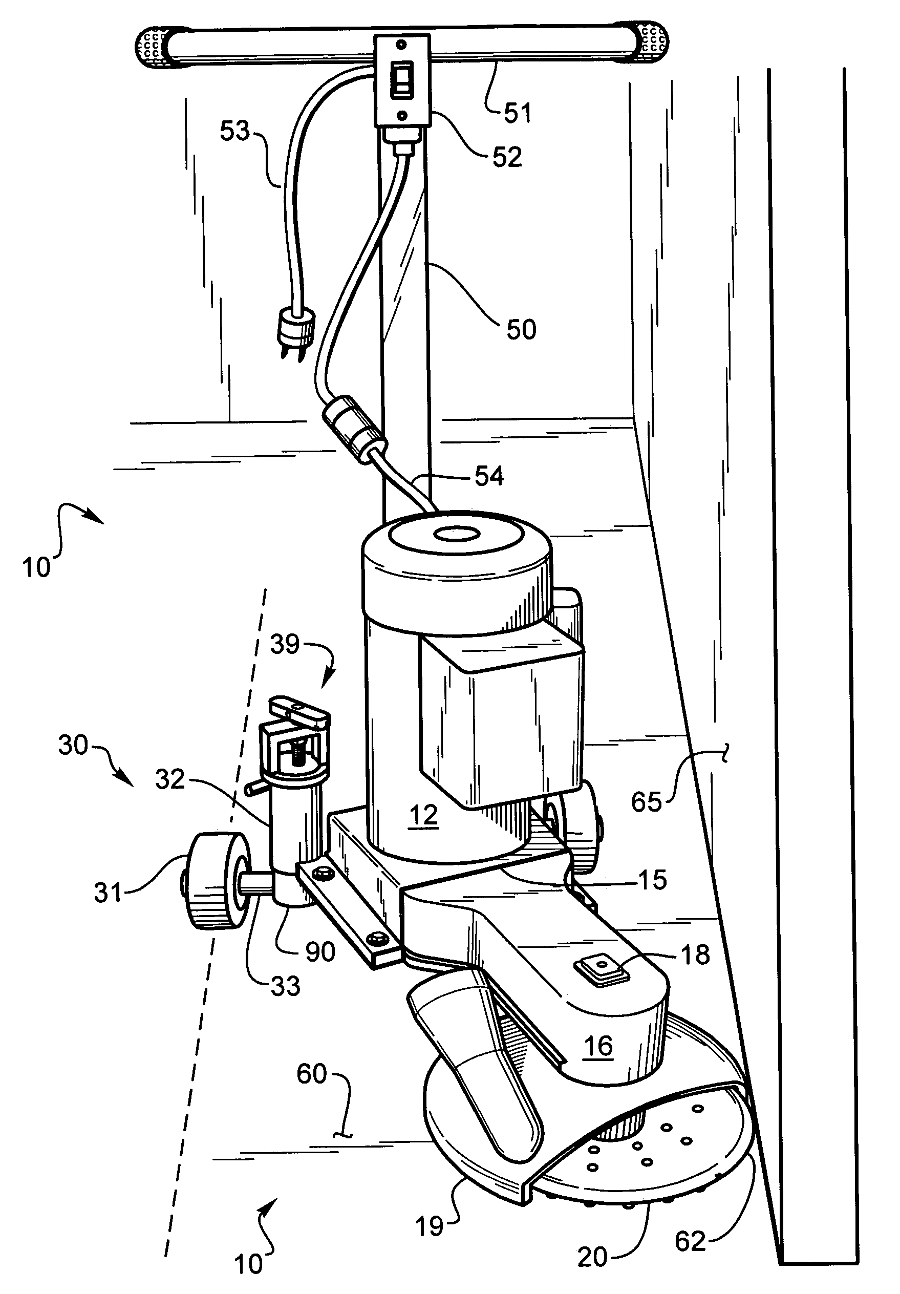
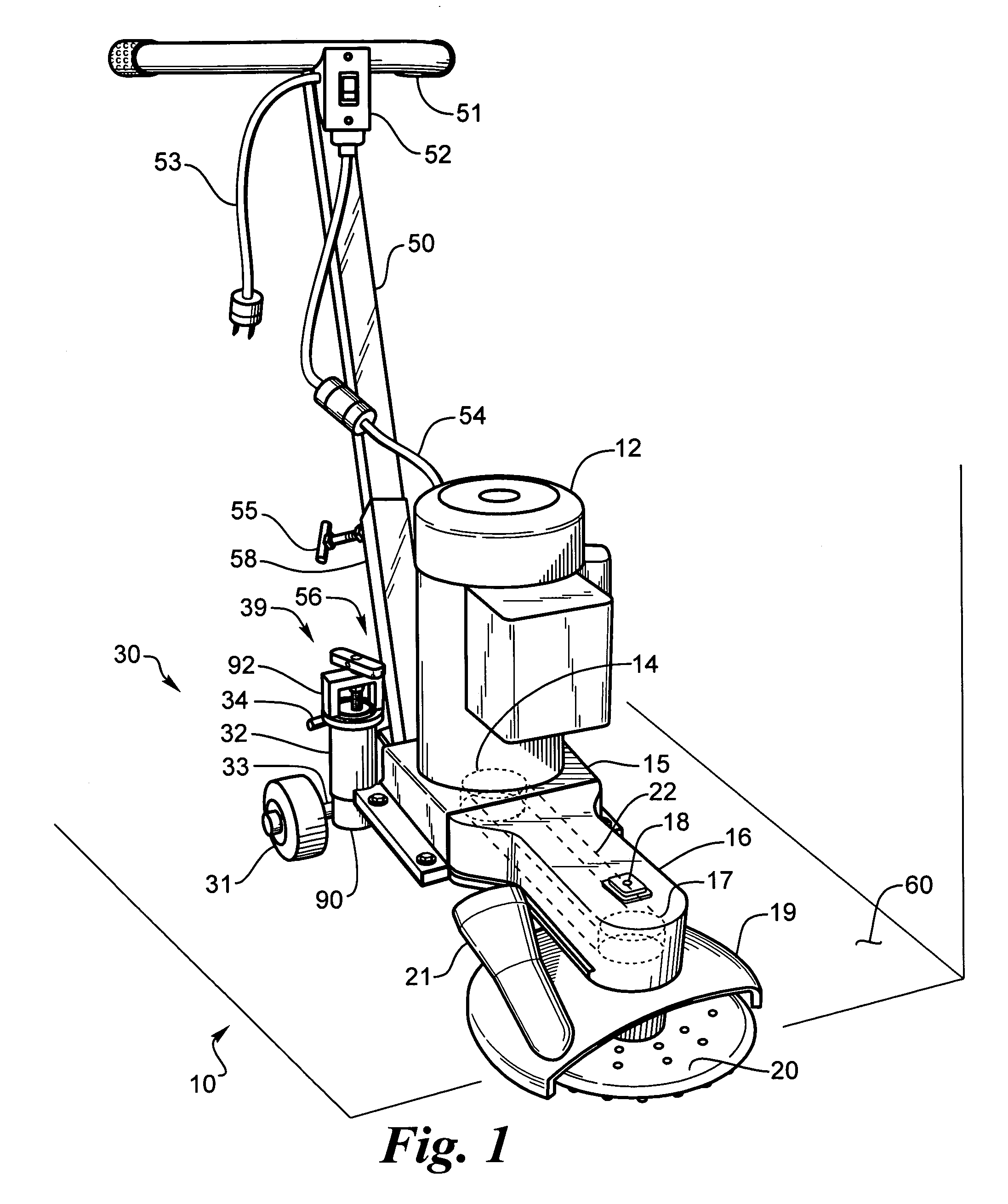
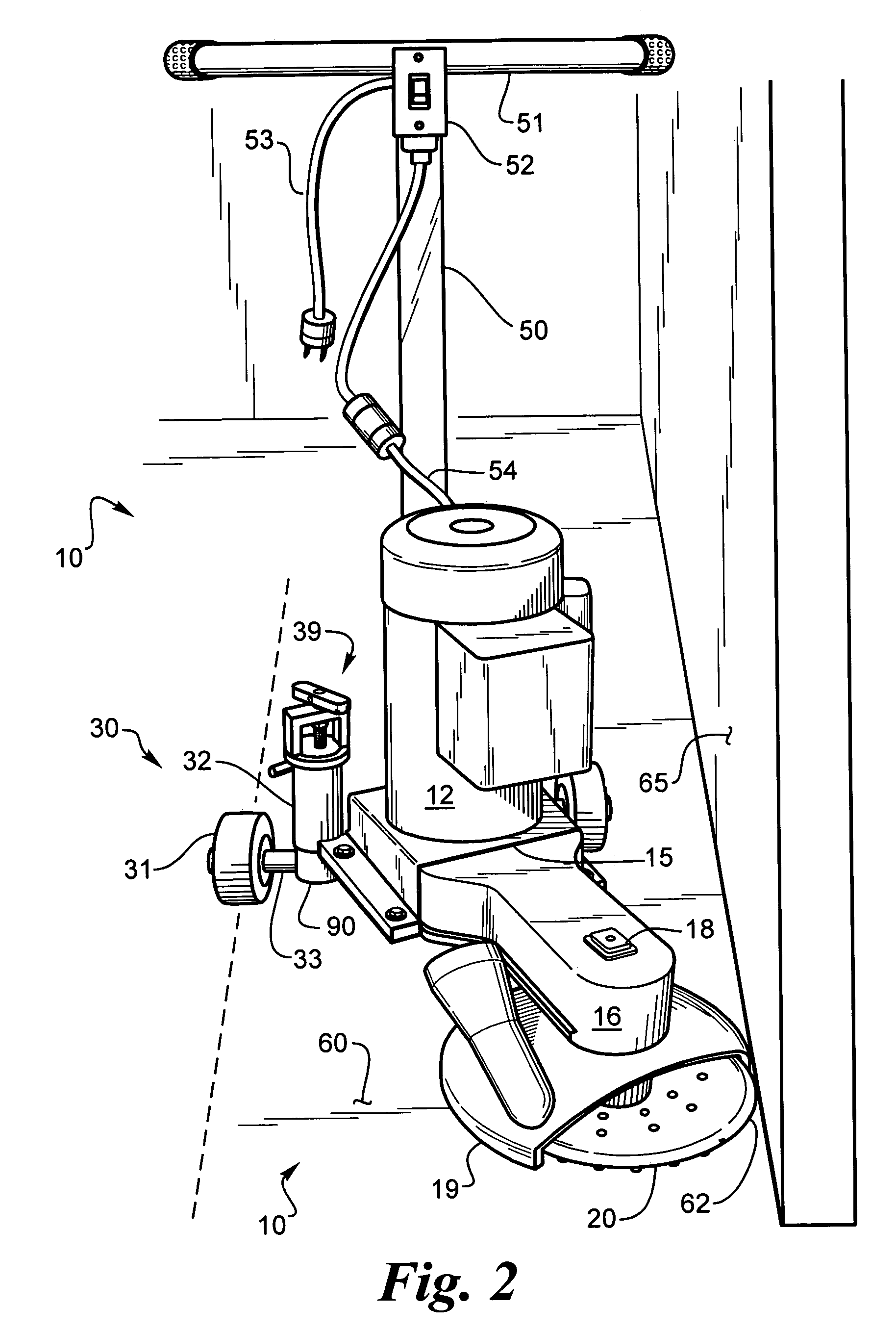
[0021]A combination of a floor grinding machine and edging machine 10 is shown in FIG. 1. In FIG. 1 the machine is used as a floor-grinding machine with the disk 20 flat on the floor 60. The base of wheels 31 are at the same height as the base of the grinding disk 20. As shown in this embodiment a shroud 19 covers most of the disk 20 and has a vacuum hose attachment 21 for removing the dust created by grinding the floor 60. A vacuum, not shown, sucks the dust and particles from the shroud 19 to keep the floor 60 clean and improve the grinders ability to contact the floor 60 for better grinding performance. The shroud 19 may be a full shroud or it can have the tip left open for engaging walls with the grinding disk 20 without interference from the shroud 19. The shroud 19 may pivot for adjusting the opening to the side of the shroud. The shroud 19 may be changed to a different size when the disc 20 is changed to a different size. In an alternative embodiment the shroud 19 may also be...


PUM


Abstract

A combined floor edger and grinder having a grinding disk which can be adjusted from engaging the floor while flat to engaging the floor along a front, back or side edge of the disk, depending on the height adjustment of the wheels on either side of the frame. The wheels, shroud and handle can also be adjustable relative to the frame for moving the frame straight back and forth or at an angle such that with the disk adjusted to engage the floor on one side of the frame the wheels and handle can be adjusted such that they are angled with respect to a wall for use as an edger whereby a user can push the device along the edge of a wall in a straight line while edging. The shroud and disk sizes may be easily changed for different jobs. The shroud can be open or close ended.

Description

BACKGROUND OF THE INVENTION[0001]1. Field of the Invention[0002]This invention relates to floor grinding machines for cement and other floors and more particularly to adjustments on the floor grinding machine to tilt the grinding disk to different positions for grinding the floor and turning the grinding machine into and edger.[0003]2. Description of the Related Art[0004]There are floor grinding machines which have a grinding disk which rotates to grind floors. The disk lays flat on the floor and the floor grinding machine is moved over the floor surface to grind the floor surface.[0005]There are special floor grinders which can be hand held and guided for grinding floors along walls. These edging machines may have a smaller disk and are more labor intensive due to the small disk size and the necessity to guide the edger along the wall by hand. Other hand held grinders are used to grind down one high point in a floor, which needs to be smoothed down. For this purpose the edge of a d...

Claims


Application Information

Patent Timeline
IPC IPC(8): B24B23/00A47L5/00B24B27/08E01H1/08
CPCA47L11/162A47L11/4072B24B7/186
Inventor ANDERSON, MARTIN L.
Owner NAT FLOORING EQUIP INC
Why Eureka
Try Eureka