System and method for sidelobe reduction using point spread function expansion

a function expansion and sidelobe technology, applied in the field of radar systems and methods, can solve the problems of preventing the return signal from being properly distinguished, the return signal produced has a correspondingly low energy, and it is difficult to detect and accurately calculate the range of two or more closely spaced targets, so as to reduce the sidelobe of the doppler filter, increase the mainlobe width, and reduce the effect of sidelobes

Inactive Publication Date: 2007-07-24
INFORMATION SYST LAB
View PDF12 Cites 10 Cited by
  • Summary
  • Abstract
  • Description
  • Claims
  • Application Information

AI Technical Summary

Benefits of technology

[0013]In some implementations of the present invention, Doppler frequency is used together with range to optimize the complex coefficients. In greater detail, for Doppler filtered return signals, the PSF for use in the expansion expression is generated in two-dimensional (range×Doppler) space. For these implementations, the present invention allows the target velocity to be calculated (in addition to target size and location). In addition, certain embodiments of the present invention are disclosed which can reduce Doppler filter sidelobes without increasing mainlobe width, and as a consequence, increase target detection accuracy.

Problems solved by technology

When pulses having relatively long pulse durations are employed, it is often difficult to detect and accurately calculate the range of two or more closely spaced targets.
Specifically, with long pulses, the scattered returns from closely spaced targets overlap, preventing the return signals from being properly distinguished.
When pulses having insufficient energy are used, the return signals produced have a correspondingly low energy, and cannot be detected.
One reason pulse energy becomes important when contemplating the use of short pulses, is that radar systems are limited in terms of peak power.
As a consequence, these radar systems, by themselves, cannot produce a short pulse having sufficient energy to detect relatively small targets.
Unfortunately, during this process, so-called “time-sidelobes” are created and show up together with a peak in the pulse-compressed signal.
In the absence of a suitable technique to overcome this problem, small targets that are in close proximity of a large target may be undetectable.

Method used


Image

  • System and method for sidelobe reduction using point spread function expansion
  • System and method for sidelobe reduction using point spread function expansion
  • System and method for sidelobe reduction using point spread function expansion

Examples


Embodiment Construction

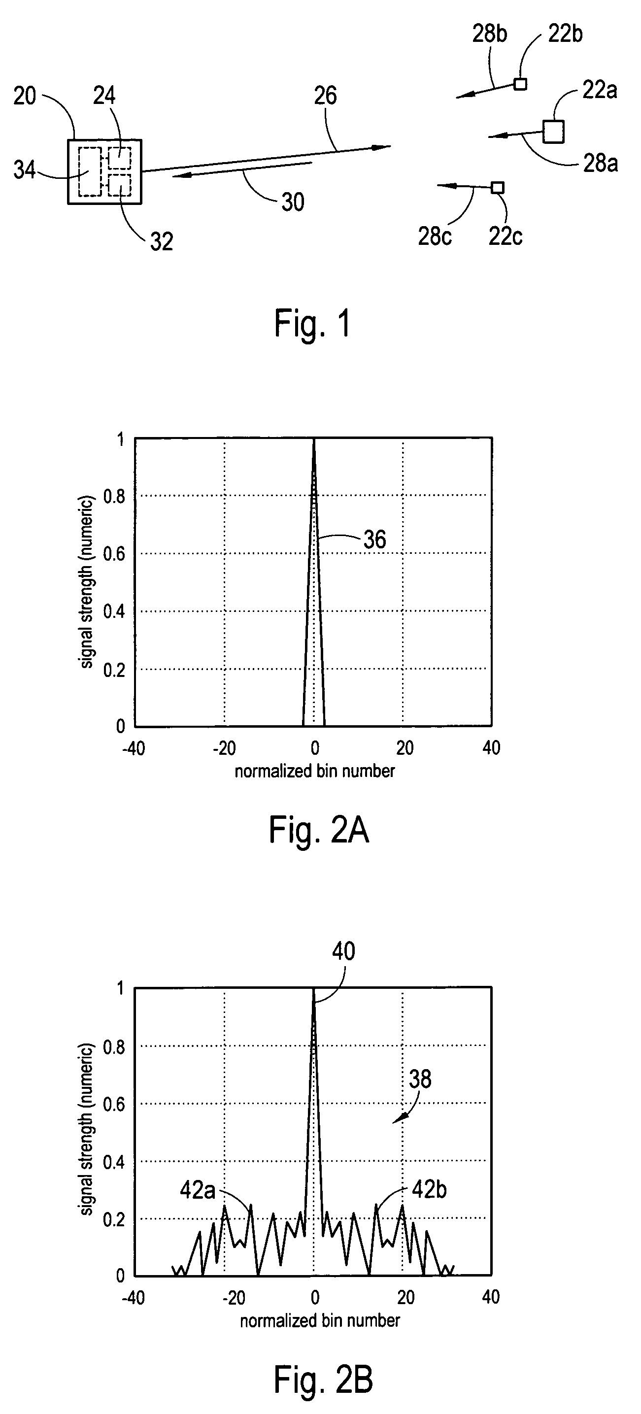
[0023]Referring to FIG. 1, a radar system 20 is shown for detecting a plurality of targets, such as exemplary targets 22a-c shown. Although three targets 22a-c are shown in FIG. 1, it is to be appreciated that more than three and as few as one target 22 can be detected with the system 20. As further shown in FIG. 1, the radar system 20 can include a radar transmitter 24 configured to generate and transmit a coded pulse signal 26. The transmit signal 26 typically consists of a pulse train having one or more pulses. For the system 20, the transmit signal 26 can be modulated with a pre-selected waveform. Suitable waveforms can include, but are not necessarily limited to: 1) a pseudo-random coded waveform, and 2) a linear frequency modulated (LFM) (e.g. chirped) waveform.

[0024]Continuing with FIG. 1, it can be seen that the transmitted signal 26 is scattered by each target 22a-c generating a respective target scatter signal 28a-c. These scatter signals 28a-c combine to create a return s...


PUM


Abstract

Systems and methods for detecting targets using pulse-compressed radar signals are disclosed. In one application, relatively small targets that are masked by the time-sidelobes of a larger target's return signal can be detected. The methods include a signal expansion type algorithm that is used to process the pulse-compressed return signal. Specifically, a generalized Fourier expansion expression having a summation of PSF terms is used to expand the pulse-compressed signal. Each term represents a respective target and includes a point spread function and a complex coefficient. The signal expansion procedure can be used to determine a set of optimum complex coefficients, with one coefficient for each range bin. Doppler frequency can be used together with range to optimize the complex coefficients. Next, targets are detected by analyzing each range bin to determine whether the corresponding complex coefficient has an absolute magnitude greater than a pre-determined threshold.

Description

[0001]The U.S. Government has a paid-up license in this invention and the right in limited circumstances to require the patent owner to license others on reasonable terms as provided for by the terms of Contract No. F30602-03-C-0240 awarded by the Missile Defense Agency, Rome AFRL / SNR.FIELD OF THE INVENTION[0002]The present invention pertains generally to radar systems and methods for detecting a plurality of closely spaced targets. More particularly, the present invention pertains to systems and methods that use pulse-compressed radar signals for target detection. The present invention is particularly, but not exclusively, useful for detecting a relatively small target that is located in close proximity to a relatively large target.BACKGROUND OF THE INVENTION[0003]Pulse radar systems are capable of detecting remote targets and measuring the position (e.g. range), the radar cross section (i.e. size) and the velocity of the detected targets. When pulsed signals are used, the time per...

Claims


Application Information

Patent Timeline
Patent Type & Authority Patents(United States)
IPC IPC(8): G01S13/52
CPCG01S13/284G01S13/5246
Inventor OHNISHI, KATSUMI
Owner INFORMATION SYST LAB
Why Eureka
Try Eureka