Conveyor device and image forming apparatus

a conveyor device and image forming technology, applied in the direction of electrographic process apparatus, packaging, instruments, etc., can solve the problems of inability to provide front and rear faces, frequent colliding or pushing of the cap, and inability to provide folds, etc., to achieve convenient range, improve the configuration of the conveyor device, and maintain the rigidity of the container bag.

Inactive Publication Date: 2007-07-24
RICOH KK
View PDF16 Cites 71 Cited by
  • Summary
  • Abstract
  • Description
  • Claims
  • Application Information

AI Technical Summary

Benefits of technology

[0016]In view of the above-described background, an object of the present invention is to provide a conveyor device in which the rigidity of a bag of a container is within a practically preferable range, and a cap of the container can be placed in the right position without reducing convenience for the operator, and to provide an image forming apparatus including the conveyor device.
[0017]One aspect of the present invention provides a conveyor device including a container support for supporting a detachable container in which a substance stored in a flexible bag is discharged through a cap provided at an opening of the bag while an external pressure is applied to the bag or the inner pressure of the bag is reduced to deform the bag and to reduce the volume of the bag; a conveying-path forming member that is to be coupled to the cap of the container supported by the container support and that defines a conveying path in which the substance discharged from the container is conveyed to a destination; a cap holder movable between a holding position to couple the cap of the container to the conveying-path forming member when the container is supported by the container support and a retreating position to not hinder loading or unloading of the container into or from the container support; and a positioning unit for placing the cap holder in the holding position.

Problems solved by technology

However, the cap frequently collides with or is pushed by other things during distribution and handling before loading.
Since the bag of the toner container is flexible, the posture of the cap is interfered with by such a collision or pushing.
However, folds are not provided on front and rear faces (left and right sides of the plane of the figure) of the bag.
Therefore, the cap tends to tilt toward the front or rear face of the bag and interferes with its posture, as shown in FIG. 13.
In particular, since a portion of the bag near the cap is tapered so that inner toner easily concentrates at the cap during a toner supply operation, the posture of the cap is prone to be interfered with.
Therefore, the nozzle of the toner-conveying device is not properly coupled to the cap, and a normal toner supply operation cannot be performed.
Although the operator can correct the posture of the cap before loading, this is troublesome for the operator, and convenience for the operator is substantially reduced.
Even when the cap is in a correct posture before loading, if the cap collides with something while the toner container is being loaded in the toner-conveying device, the posture of the cap is easily interfered with because the bag of the toner container is flexible.
Therefore, the operator also must take care so that the posture of the cap will not be interfered with during loading of the toner container, and this reduces convenience.
While the operator generally loads the toner container while holding the bag, it is difficult for the operator to correct the posture of the cap by handling the held portion.
Since the bag is flexible, a force applied to the held portion by the operator is not easily transmitted to the cap, and it is difficult for the operator holding the bag to control the position and posture of the cap.
In this method, however, since a sheet material that forms the bag is thick, heat is not easily transmitted to the inner side of the sheet material during a seam-welding process for welding a seam of the sheet.
For this reason, welding failure may occur, or the strength may decrease.
To prevent welding failure or a decrease in strength, time taken for the seam-welding process must be increased, and the manufacturing cost of the bag increases.
Consequently, the bag does not take a desired shape after volume reduction, but deforms into an undesirable shape along the creases.
In this method, however, the thickness of the sheet material of the bag is reduced, and a portion of the bag near the cap is first crushed at the early stage of the volume reduction process.
When the portion is crushed, discharging of toner from the toner container is hindered, the amount of toner to be discharged varies, and much toner remains in the toner container.
Furthermore, since the operator generally holds the bag, as described, when the bag is too soft, ease of handling and convenience are reduced.
From the above viewpoints, there is a practically desirable range of rigidity of the bag in the toner container, and it is difficult to overcome the above problems in the range by preventing the posture of the cap from being interfered with.
The above problems occur not only to the mechanism for supplying toner from the toner container to the developing device, but also to a mechanism for conveying a material stored in a container made of a flexible material to other devices.

Method used


Image

  • Conveyor device and image forming apparatus
  • Conveyor device and image forming apparatus
  • Conveyor device and image forming apparatus

Examples


Embodiment Construction

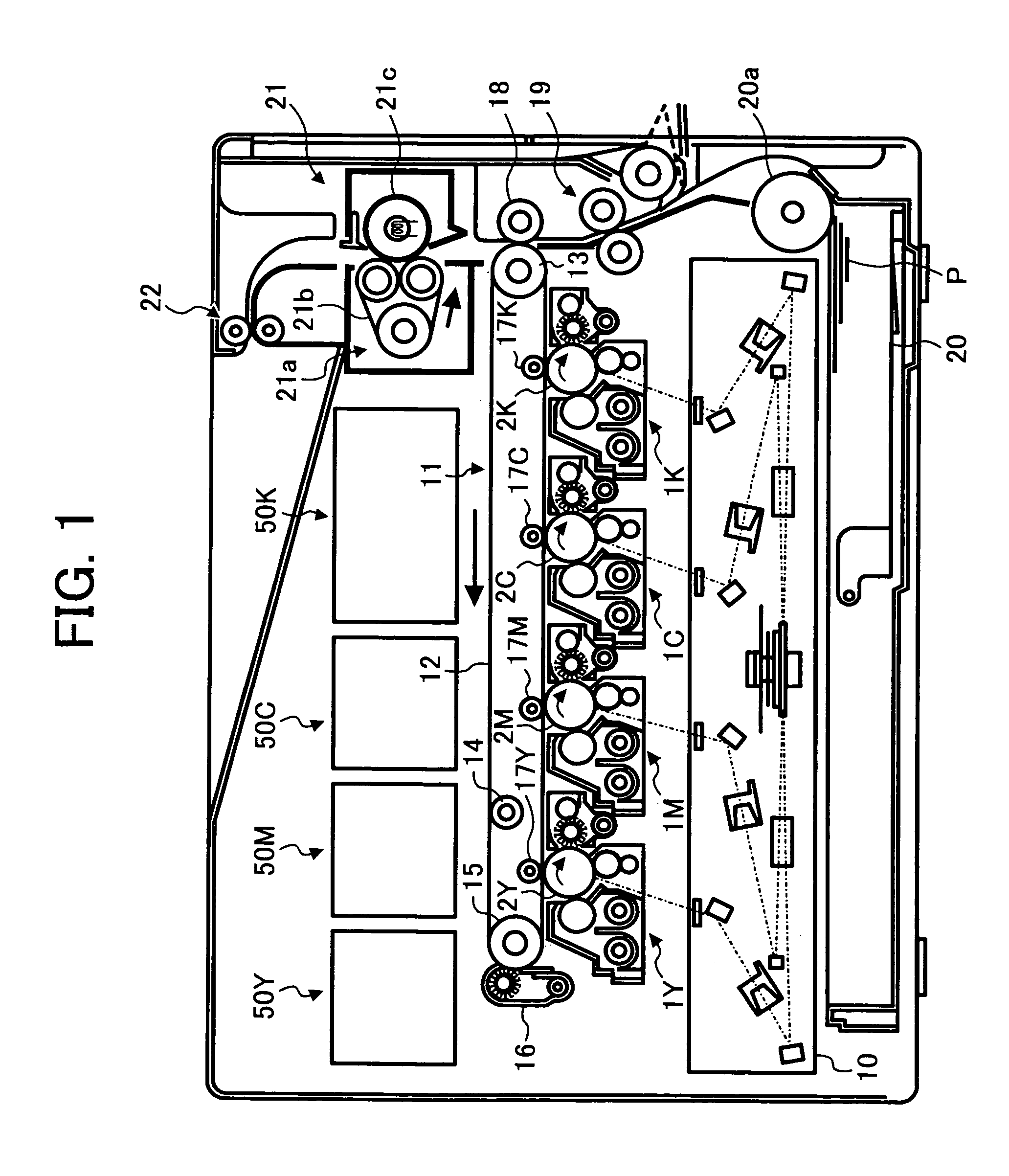
[0052]In describing preferred embodiments illustrated in the drawings, specific terminology is employed for the sake of clarity. However, the disclosure of this patent specification is not intended to be limited to the specific terminology so selected and it is to be understood that each specific element includes all technical equivalents that operate in a similar manner. Referring now to the drawings, wherein like reference numerals designate identical or corresponding parts throughout the several views, particularly to FIG. 1, a tandem color laser printer (hereinafter simply referred to as a “printer”) including a plurality of photosensitive members arranged side by side will be described below as an image forming apparatus according to an embodiment of the present invention.

[0053]First, the basic configuration of the printer will be described.

[0054]FIG. 1 is a schematic structural view of the printer of this embodiment. The printer includes four process units 1Y, 1M, 1C, and 1K f...


PUM


Abstract

A toner-conveying device includes a movable plate. The movable plate is movable between a holding position such as to couple a cap of a toner container to a nozzle when the toner container is supported by a container holder, and a retreating position such as not to hinder loading or unloading of the toner container in the container holder. The movable plate is placed in the holding position by a cam when the nozzle is coupled to the cap, and is released and moved to the retreating position while the toner container is being loaded or unloaded. In this structure, the cap can be properly positioned in the conveyor device while ensuring the rigidity of a bag of the container within a practically preferable range, without reducing the convenience for the operator.

Description

BACKGROUND OF THE INVENTION[0001]1. Field of the Invention[0002]The present invention relates to a conveyor device for conveying, for example, powder, liquid, or gas stored in a flexible container to other devices, and to an image forming apparatus that uses the conveyor device as a toner-conveying device.[0003]2. Description of the Related Art[0004]This type of conveyor device is used in various technical fields. For example, conveyor devices disclosed in Japanese Unexamined Patent Application Publication Nos. 2001-194907, 2001-324863, and 2002-72649 are used in the field of an image forming apparatus. These conveyor devices are used as toner-conveying devices that supply toner from a toner container to a developing device. The toner container mounted in the toner-conveying devices is made of a bag-shaped flexible material, and can be contracted and reduced in volume by a suction force of a suction pump. The shape and size of a hard toner container, such as a cartridge or a bottle,...

Claims


Application Information

Patent Timeline
Patent Type & Authority Patents(United States)
IPC IPC(8): G03G15/08G03G15/00B65D83/06G03G15/06
CPCG03G15/0886G03G15/0849G03G15/0853G03G15/0879G03G15/0877G03G2215/0119G03G2215/0682Y10S222/01G03G15/00G03G15/06
Inventor TAKAMI, NOBUO
Owner RICOH KK
Why Eureka
Try Eureka