Expansible shoe rack

a shoe rack and expansion technology, applied in the field of shoe racks, can solve the problems of limiting the practical capacity of the shoe rack, affecting the appearance of the product, and affecting the product reputation, so as to enhance the structural integrity and rigidity of the shoe rack construction, and improve the capacity without lengthening the packaging. , the effect of easy identification

a shoe rack and expansion technology, applied in the field of shoe racks, can solve the problems of limiting the practical capacity of the shoe rack, affecting the appearance of the product, and affecting the product reputation, so as to enhance the structural integrity and rigidity of the shoe rack construction, and improve the capacity without lengthening the packaging. , the effect of easy identification

US7249679B2Inactive Publication Date: 2007-07-31LYNK

Image

  • Expansible shoe rack
  • Expansible shoe rack
  • Expansible shoe rack

Examples


Embodiment Construction

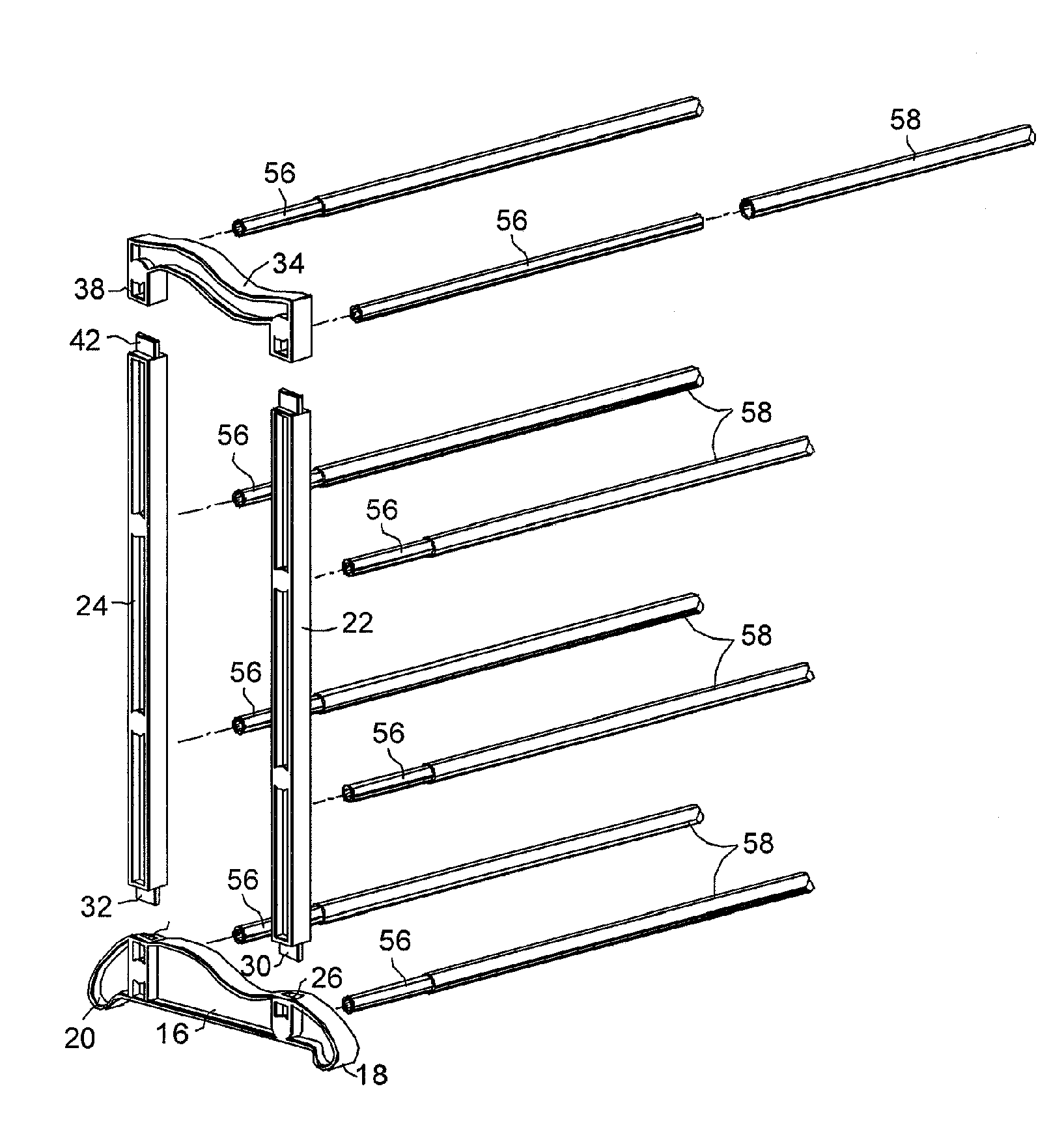
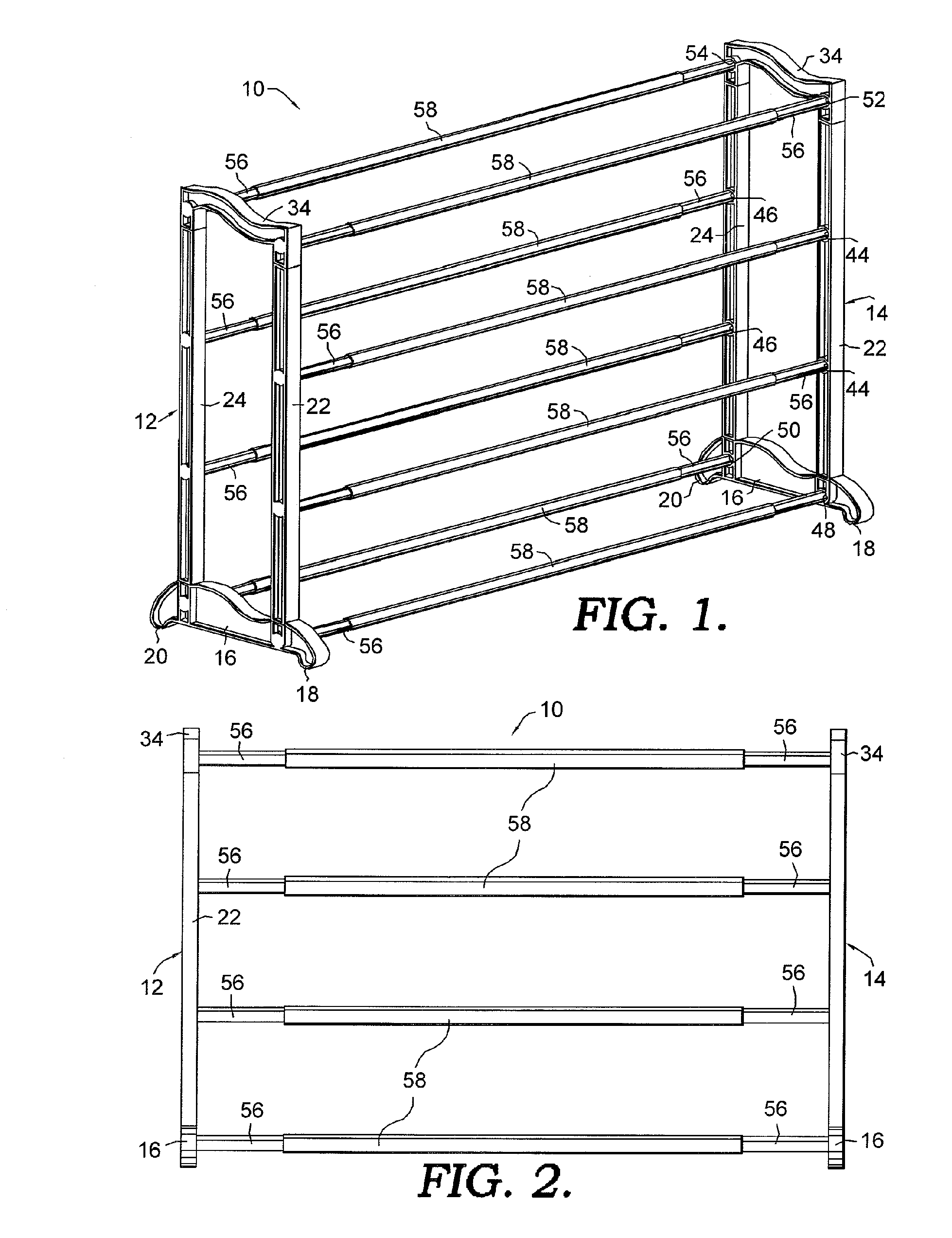
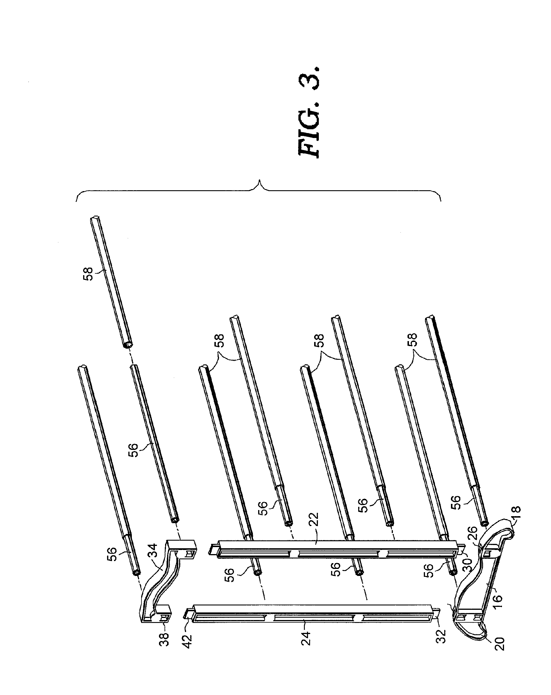
[0021]Referring now to the drawings in more detail, numeral 10 generally designates an expansible shoe rack constructed according to a preferred embodiment of the present invention. The shoe rack 10 has a frame that includes opposite sides 12 and 14 that are mirror images of one another. Each of the frame sides 12 and 14 has a base 16 that rests on a floor or other supporting surface. Each base 16 has a front foot 18 and a rear foot 20 that contact the floor. Each frame side 12 and 14 also includes a front upright post 22 and a rear upright post 24. The post 22 and 24 may have an I-beam-type construction and have detachable connections with the base 16 at their lower ends. As shown particularly in FIG. 3, each base 16 has a slot 26 near its front end and another slot 28 near its rear end. The lower end of post 22 is provided with a tongue 30 on its lower end which may be press fit into the forward slot 26. Each of the rear posts 24 similarly has a projecting tongue 32 on its lower e...


PUM


Abstract

A self-standing shoe rack or other type of shoe rack such as a hanging shoe rack which can expand lengthwise due to telescoping shoe support bars. Opposite frame sides may have equal-size sockets that receive identical end tubes. The end tubes fit telescopically in center tubes to allow length adjustment.

Description

CROSS-REFERENCE TO RELATED APPLICATIONS[0001]Not applicable.STATEMENT REGARDING FEDERALLY SPONSORED RESEARCH OR DEVELOPMENT[0002]Not applicable.TECHNICAL FIELD[0003]This invention relates generally to shoe racks and more particularly to a self-standing shoe rack or other type of shoe rack that can be expanded to vary its capacity for holding shoes.BACKGROUND OF THE INVENTION[0004]Efforts have been made to provide shoe racks that can be expanded and contracted in order to vary their capacity and allow them to fit in whatever area is available. For example, U.S. Pat. No. 3,888,353 to Leifheit and U.S. Pat. No. D403,880 to Malik disclose shoe racks having telescoping tubes on which shoes are supported. The tubes can be adjusted telescopically in length to vary the length and capacity of the shoe rack. However, in both of these shoe racks, there are two telescoping tubes that have different diameters, and the sockets that receive the tubes on the shoe rack frame must have different size...

Claims


Application Information

Patent Timeline
31 Jul 2007
Publication
US7249679B2
IPC
A47F7/08
CPC
A47F7/08
Inventors
KLEIN, RICHARD B.